Category Archives: reprap

Learn From My Fail

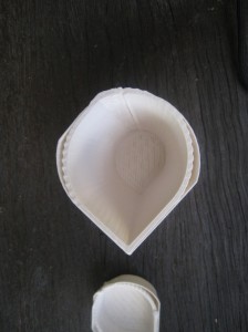
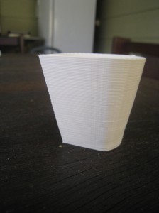
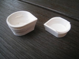
If you’ve been following the blog, you’ll have seen that I recently replaced the pulleys with aluminium pulleys. I’ve also been having trouble with my shells not lining up. Until yesterday, I hadn’t put two and two together, and realise that one was causing the other.

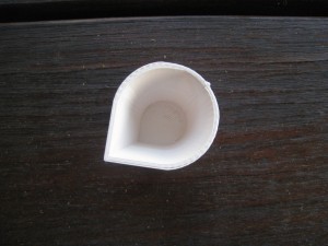
I put a post on the Reprap Skeinforge forum, showing the shot glass, and asking what might the problem be. I thought it must have been an SF issue, but the forumer’s quickly suggested that the problem was probably with backlash.

Nophead then suggested that the problem was probably the aluminium pulleys. He stated that the teeth on the pulleys are too narrow, and cause the belt to slop around on the teeth. So I pulled the Aluminium pulleys off, and replaced them with the original RP pulleys.

What a difference. So, learn from my fail, the ebay Aluminium pulleys are worthless. Video of the shot glass being printed:

Slowdown

As I mentioned in my previous post, I had issues with the last print due to the high speed. I thought I’d slow this one down.

I also thought that I should be more meticulous about keeping records of the changes I’m making. In keeping with the original ‘lab notebook’ idea for this blog, here’s the settings.

Original settings:

From ‘Speed’

  • Main Feed Rate – 60 mm/s
  • Perimeter Feed Rate – 30 mm/s
  • Travel Feed Rate – 130 mm/s
From ‘Raft’
  • First Layer Main Feed Rate – 35 mm/s
  • First Layer Perimeter Feed Rate – 25 mm/s


Changed Settings:

From ‘Speed’

  • Main Feed Rate – 20 mm/s
  • Perimeter Feed Rate – 15 mm/s
  • Travel Feed Rate – 30 mm/s
From ‘Raft’
  • First Layer Main Feed Rate – 15 mm/s
  • First Layer Perimeter Feed Rate – 15 mm/s

And the result:

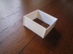
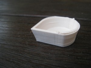
As you can see, it came out looking nearly identical to the first part. So it looks like speed isn’t the problem. As another test, I decided to print out the ‘single wall calibration piece’. It came out beautifully.

Then I thought I’d try the 10x40mm piece. I stopped that one after about 8mm, it was just turning into a sludgy mess. I thought then that to print a piece like that, I’d need to turn down the temperature, or use active cooling. I thought I’d try turning the temp down.

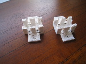
To get a better picture of what was happening, I thought I’d print out the ‘ultimate calibration piece’. To start with, I turned the temp down to 225 degrees, (from 230).

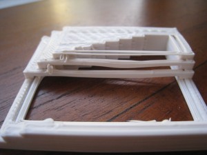
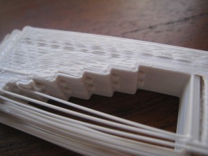
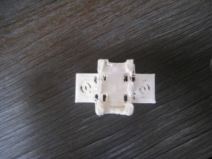
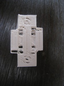
You can see in the picture, that the first couple of ‘hanging beams’ are sagging a bit. I then turned the temp down to 220. The remainder of the object printed fine, but the sagging was noticeably reduced.

I stopped the print at that point, since the ‘shelling’ problem (can be seen in the problem above) was distracting me. It’s clearly seen in the ‘reprap shot glass’, and it looks like SF is not correctly shelling the object, and creating proper G-Codes. I thought I’d better fix that problem first, before messing with the temperature.

Overthinking the Problem

One of the things I try and teach younger engineers (whenever they’ll listen – damn Gen Y’ers) is that it’s possible to over-think a problem. You end up burrowing down so much that you become entangled in the work, and generally end up with a much more complicated solution than what’s actually required.

When thinking about changes that I had to make to skeinforge, I realised that I had too many variables – one of the classic symptoms of over-thinking. I had made too many changes to the original settings, and I wasn’t sure which ones I needed to change back, or other ones to change.

So I decided to take a step back, approach the problem from the start again. To do that, I deleted the skeinforge directory, and re-installed from latest download – going back to the original skeinforge settings, no adjustment at all. This would allow me to approach the problem fresh. I went back and re-did the shot glass.

 It’s looking great. Still a bit strange, but vertically, it’s just about perfect.

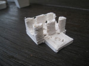
Emboldened by this success, I thought that I’d try and print out a useful part – a LM8UU Y-axis bearing holder. After looking at the options on Thingiverse, I finally settled for Digifab’s design.

Classic overspeed melted mess. That makes sense. When I did the shot glass, it was at original SF speed, up to 60mm / s. That was clearly way to fast for such a small piece as this. I’ll try it again tonight, but at a much slower speed.

The heatbed is working great. No problems at all getting the prints to stick.


J-Head Hot End

After my meltdown, I bought two hot-ends. One was the Budasnozzle, with which I’m currently printing. The other, which just arrived yesterday, is the J-head Mk 3-B, which I bought from hotends.com.

Since I’m very happy with the Budasnozzle, I won’t bother using this one at the moment. I’ll just put it in the drawer as a spare part, or to provide it to a fellow Aussie who gets in distress with his printer.

Back to Printing

This afternoon, I re-assembled the printer. The differences are the Budasnozzle, and the stepper motors with their flats and pulleys.The Budasnozzle’s attachment really makes it easy to attach. Full marks for the designer.

My only problem with getting the printer running was that the hot-end was not warming up. A quick going-over with the multimeter showed a bad connection in going to the nozzle, which was quickly fixed up.

To print, I thought that I’d try the shot glass again, to give me a good idea of the differences between the old set up and new.

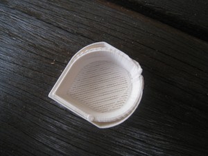
As you can see from the photos, the backlash is all but gone. The aluminium pulleys really make a massive difference here.

As I can see it, there’s three problems now.

Problem 1. Flat side on the print.

Solution 1. I suspect that the wires going to the hot-end are too tight (the Budasnozzle’s lines are shorter than the Arcol’s). Check tightness, and loosen off if necessary.

Problem 2. Extra shell around the outside of the print.

Solution 2. Turn retraction back on.

Problem 3. Base not quite filled in enough.

Solution 3. Infill feed rate

Hopefully, those problems should have the prints looking good.

Budasnozzle

After my disastrous hot-end meltdown, I tried to order in some parts for my Arcol hot-end. Unfortunately, Laszlo was out of parts for his hot end, so I had to go looking around for other alternatives. In the end, I bought two, with one to have as a backup. One hot-end I found is still to arrive, but this one arrived a few days ago.

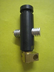
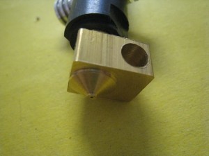
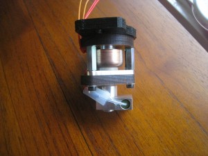
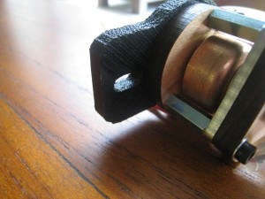
BudasnozzleIt’s the Budasnozzle, which I purchased from Lulzbot. It’s based of the Arcol design, but with some variations. It’s noticeably shorter, cutting down on the body heat-sink length, which I agree is far too long. It also uses a different type of thermistor, the slightly larger type, that looks more like a standard resistor. This type of thermistor should be much easier to replace than the ‘glass bead’ sort.

It’s very professionally built. All the parts are excellently machined, and assembled with precision, and with an eye for detail.

It’s best feature, however, is the attachment. As I’ve mentioned previously, the Acol hot-end has difficultly attaching with some extruders. The Budasnozzle has a printed base on it that has holes in the exact same locations as the extruders. So when you attach your extruder to the X-carriage, you’re also securing your hot-end. This also gives it a very large stable base to work from. An excellent approach that I think a lot more hot-ends should take.Budasnozzle mountI’ll put in action this weekend and get back to printing. Hopefully, it last longer than the last one did.

Precision Flats

Several people have recommended that having flats on your motor shafts is a good idea. After having a couple of issues with my extruder motor gear slipping, I thought that it might be a good idea, too. The suggested way of doing it is to grip your motor shaft in a vice, and then file it down.

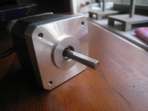
Fortunately, at my workplace, there’s a guy who’s a keen machinist. I passed the stepper motors along to him, and asked him if he could put some flats on the shafts. He thought it was a pretty easy job, and didn’t even ask for payment in beer. Here’s the results back a few days later.Stepper motor with precision flat

Now with some nice flats on the motor shafts, I thought that this would be a good time to fit the aluminium pulleys I had previously purchased. Unfortunately, the grub screws for these pulleys are far to long, they sit up into the tooth void when screwed down, causing the belt to skip over that tooth. To rectify this, I’d have to cut the screws down.

My first attempt was to cut the screw in half with a hacksaw. Unfortunately, this was a bit too much, and only left about 1mm of screw remaining. This should work in securing the pulley, but I’ll have to keep an eye on it.

For the second attempt, I just held the grub screw with a set of small pliers, and filed the end down to a shorter length. Although it was quite slow, it did the trick in getting the screw to just the right length.

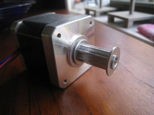
Here’s the motor with the pulley attached. It looks great, and should really cut down on backlash. The belt fits in like glue.

Stepper motor with aluminium pulley

Meltdown

Total disaster. I updated the SFact with some new settings that I had high hopes for, that I thought would take the print quality to the next level.

I turned on the hot end. After a few minutes I saw that some filament was leaking out of the hot end. Strange. Then I saw this:

The PEEK block has melted into the nozzle. PEEK’s meant to have a melting point well over 265 degrees C.

The only cause for this that I can think of is that the thermistor wasn’t quite attached to the heater-block correctly. This would then have generated an incorrect temperature reading, causing the electronics to over-drive the hot-end past the melting point of the PEEK.

Unfortunately, the printer’s going to be out of action until I can get some parts in to rebuild the Arcol hot-end. While I’m at it, I should make a list of ‘critical spares’ and consumables that I should have on hand for the printer.

Reprap Shot Glass, Second Attempt

After getting the thermistor working again, I tried printing out the rep-rap shot glass, with the new skeinforge settings. It turned out excellently.

Much, much better than the first attempt. There’s still a few problems that need sorting out. In the picture below, you can see some ‘sagging’ that occured on the right-hand side.

The ‘solid’ infill isn’t coming in as completely solid. Still needs some work here.

The base, however, looks nearly perfect. You can clearly see the join between the two pieces of kapton tape.

A huge improvement. I’m really happy with the printer now. I suspect that I could start to print out parts for the reprap. While they wouldn’t look the best, they’d have sufficient accuracy and strength to do the job.

Bases, and Filament Retraction

Since my last printings have worked fairly well, I thought that I’d try and get the base working perfectly as my next goal. So, for today’s prints, I thought I’d do some experiments with the printbed and base. I tried to use the Pyrex base both with and without the Kapton tape, and at different temperatures for both the filament and heatbed.

Using the Pyrex base without Kapton was a total failure. The filament did not stick at all, under any conditions. With the Kapton on, I tried using the heatbed at temperatures from 110 to 130, and the extrusion from 220 to 235 degrees Celsius.

I also experimented a bit with the height of the tip above the base, varying it from about 0.1 to 0.4mm. I had a few troubles with this step, as the printer wouldn’t always pick up the activation of the microswitch, and keep driving the tip into the base. Having a closer look, it seemed like the switch was occasionally getting caught up on the Z-mount, without actually activating.

I tried for a little while moving the microswitch to the top of the printer, but there’s something wrong with the Sprinter firmware. Once the microswitch was in place, with the appropriate firmware settings, the Z-axis would only travel upwards, not downwards at all. After a few attempts at this, I gave up, and returned the microswitch to the bottom. This time, however, I moved it to the right-hand-side of the machine, where it seems to get a cleaner activation, and doesn’t get caught on the Z-mounts, like it was doing on the left.

The best results obtained was when I used the Kapton tape, had the tip 0.4mm from the bed (measured with feeler gauge), and had the tip at 230 degrees. For the base, I start out with it set on 130 degrees (so that the surface was measuring 120 +), then turn it down to 110 degrees as soon as the print started.There’s not many pictures to show here, as the prints would generally fail almost instantly, or I’d stop them after the first couple of layers.

Once I had the base settings fairly well sorted, I thought then that I’d print a different minimug. This one is slightly larger, and prints vertically, instead of horizontally. I thought that with the new base, and the vertical printing it’d turn out better than the previous minimug.

Not the case, unfortunately, as you can see from the above photos. Watching it closely, it looked like the retraction wasn’t working properly. It’d retract the filament when doing a move, then take a fair while (at least 2-3cm of travel before the filament would start coming out again.The base, however, turned out quite nicely.

To fix this problem, I would have to go into SFact, and change the retraction distance. Since I didn’t know what would work, I set the value to zero, so I could work upwards from there. Since I was also fiddling with the SF settings, I thought that I’d speed up the printer to the default speed. I’d been operating with it on 1/3rd speed, so I thought that I’d fix that up, see how it went. I thought I’d also try out a different object, the thin-walled calibration object.

The first couple of tests of this object turned out dreadful, until I adjusted the retraction down to zero. The settings improved things, but I there’s still room for more improvement. I went back into SFact and make some more changes to the settings. This time, I slowed down the speed for the first layer, and bumped up the filament extrusion ratio.

Just when I was ready to try out my new extrusion and retraction settings, I had a problem with the thermistor. The electronics was no longer reading a value from it. I’ve either blown a thermistor (which seems unlikely), or I’ve got a bad connection. Most likely the latter, but I thought I’d leave that for another day.