After spending overnight drying out, the bushings were well attached to the base, and were sliding smoothly up and down the rods.
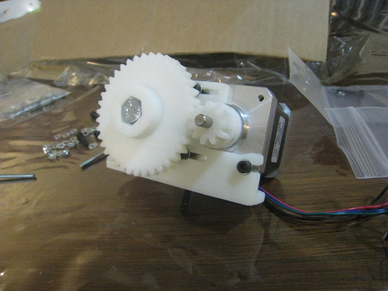
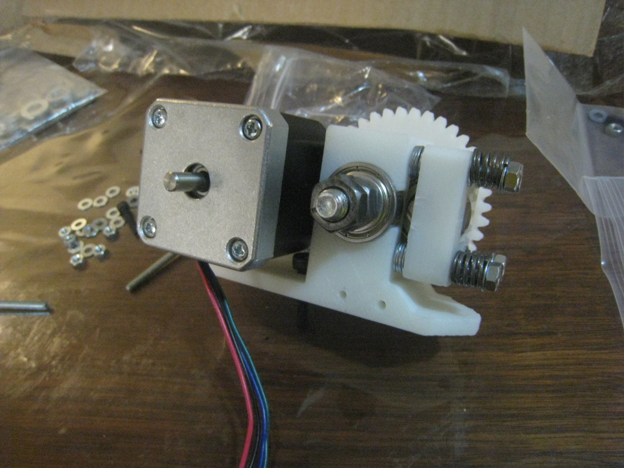
As I mentioned in my previous post, I’m a bit stuck on a couple of small points, particularly the holes I need to drill in the base-plate, but I’ll keep pushing ahead. First up for today, after measuring up the base-plate, is to attach the Y-motor, and make sure that it’s all square. Due to the lack of a 1mm allen key, I can’t attach the aluminum gears that I bought, so I’m just affixing the printed ones for now. I can definitely see the advantage in the machined gears. I have to pull the belt pretty tight to stop it from skipping over the (not perfectly sharp) gears.
Attached Y-motor
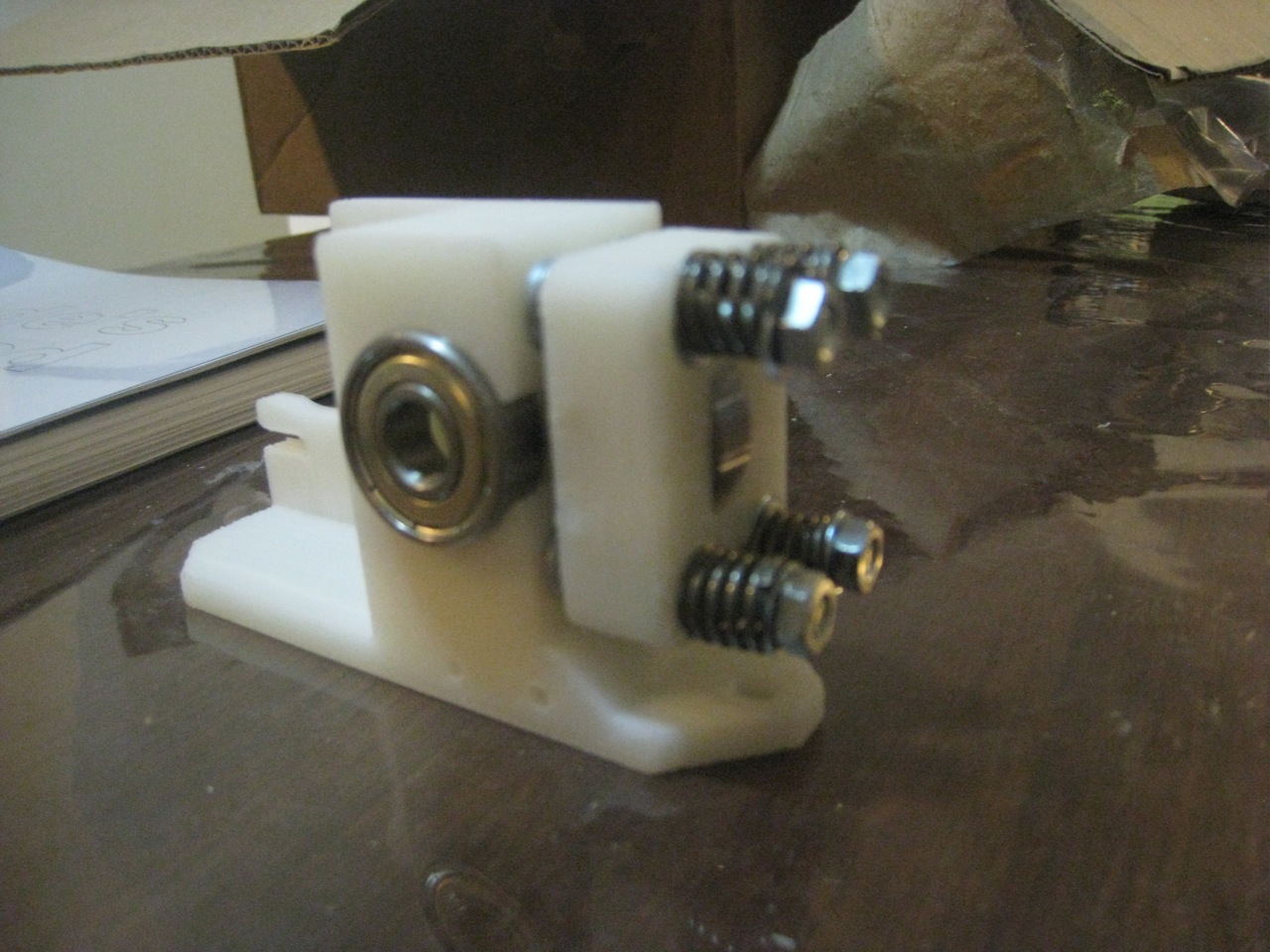
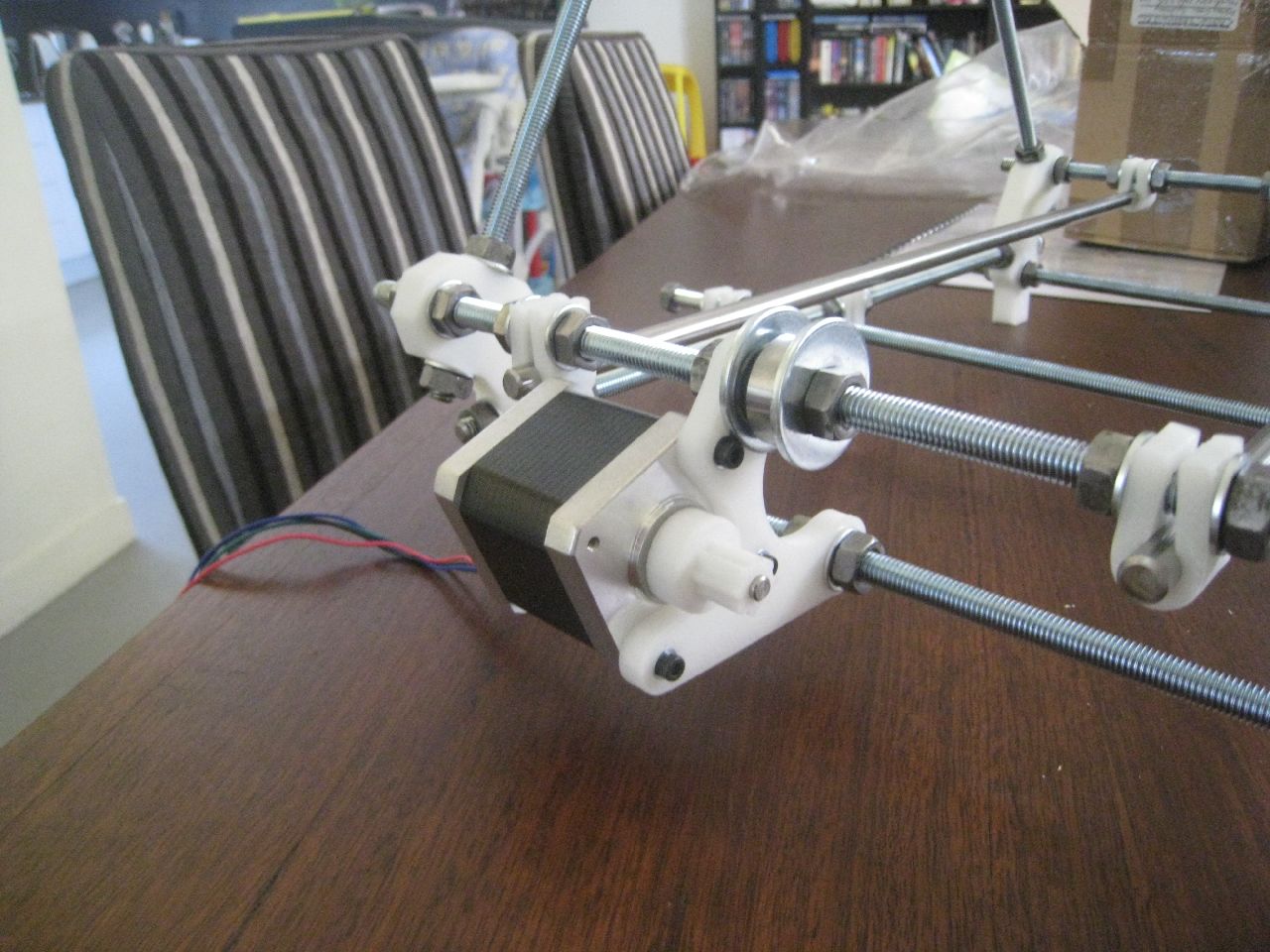
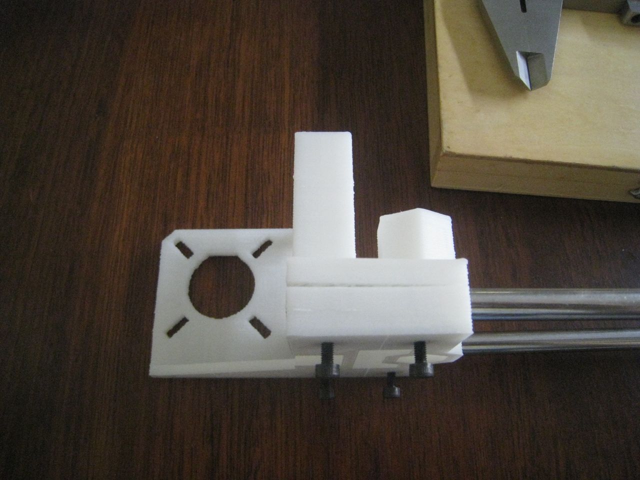
After the motor was attached, I started to work on the X-axis. This is dead simple.
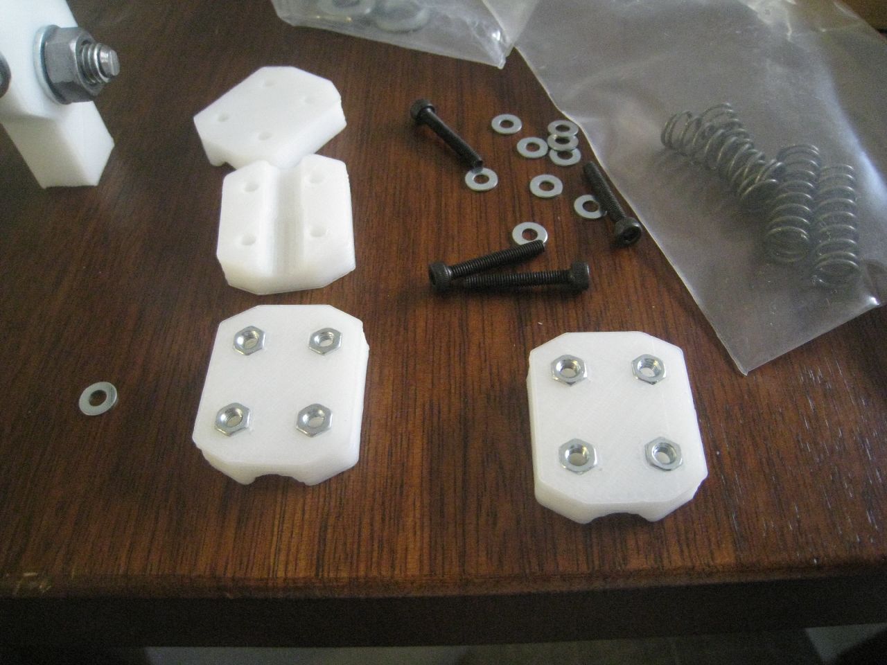
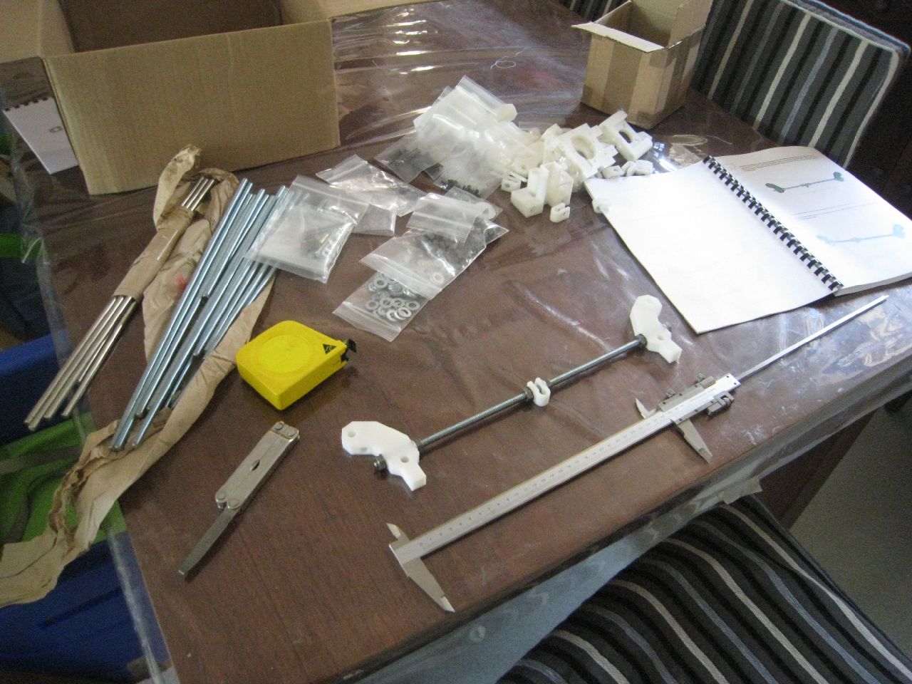
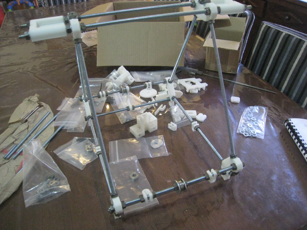
X-Axis parts
The quality of Nophead’s parts really is fantastic:
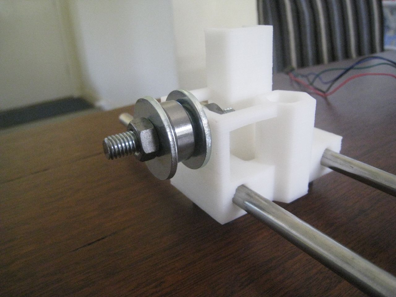
Once the X-axis was built, I set it aside on a spare chair.
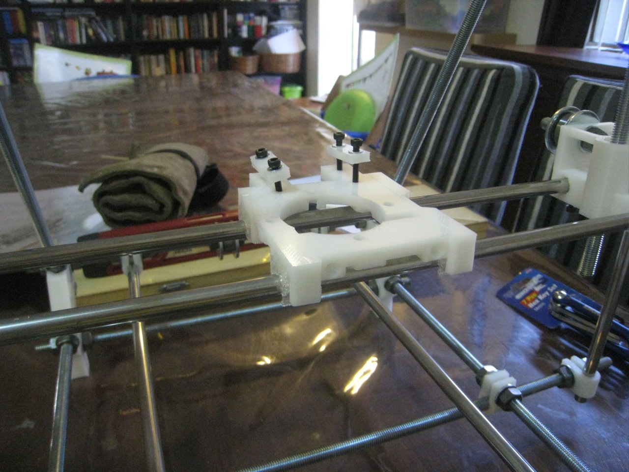
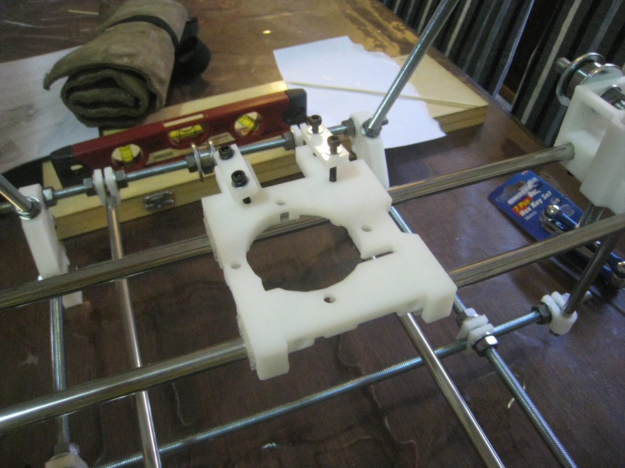
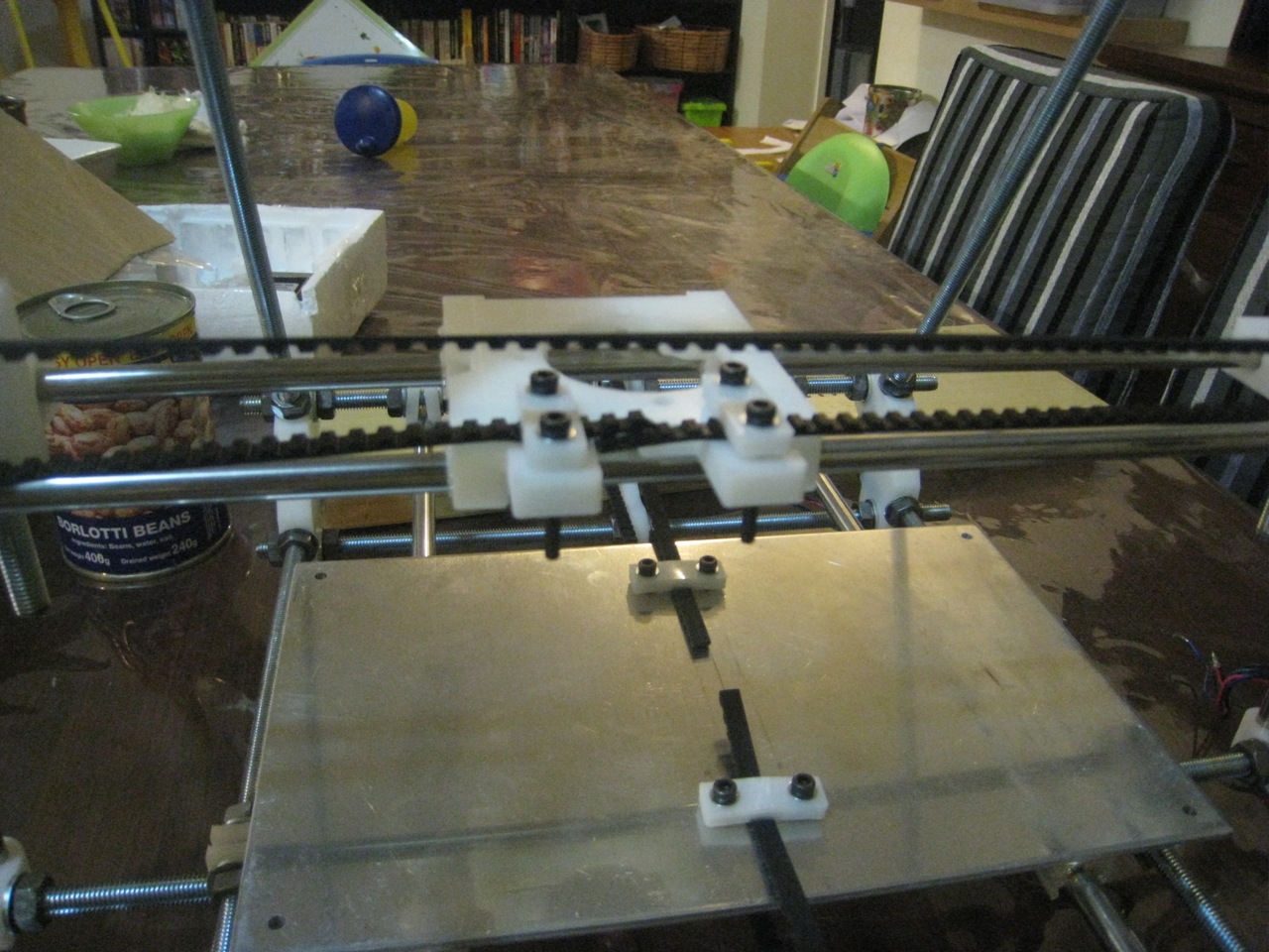
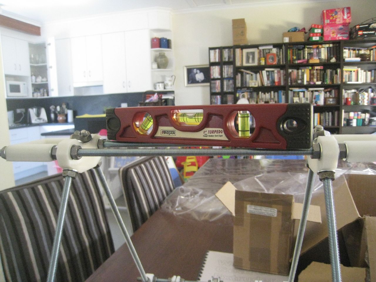
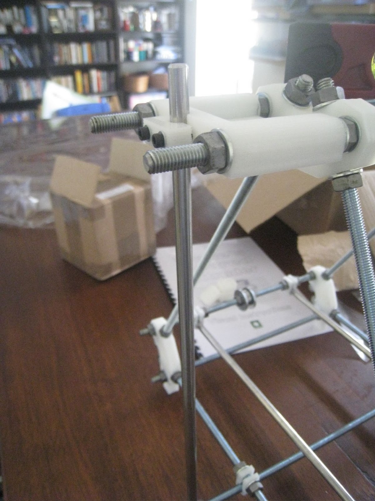
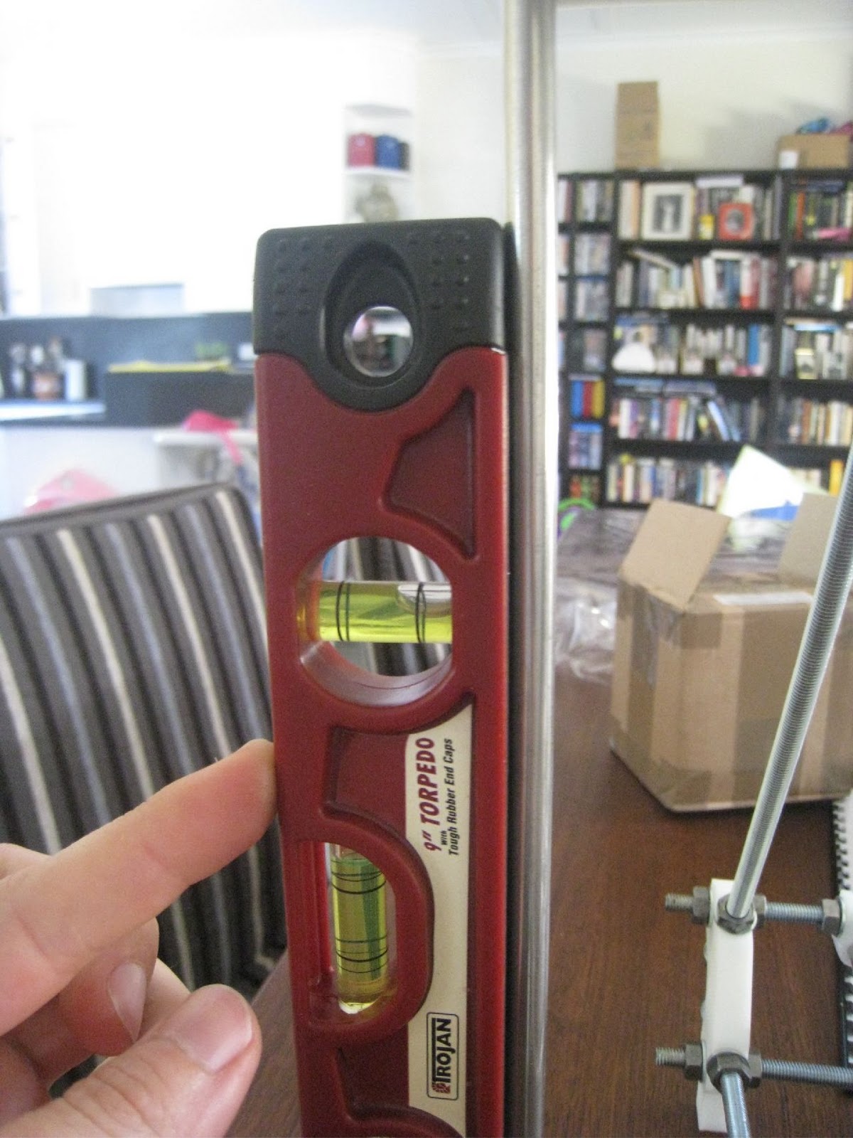
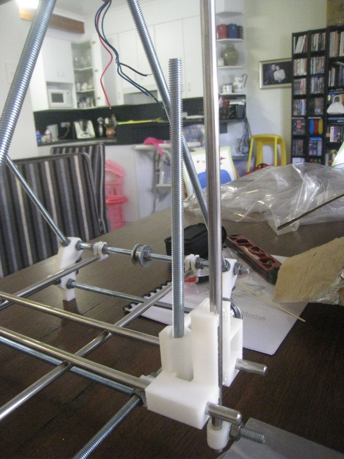
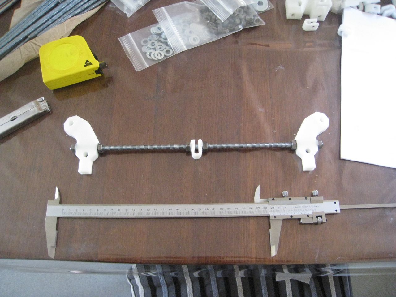
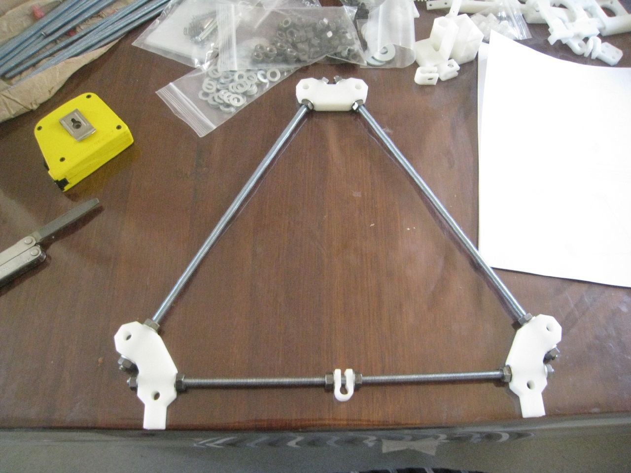
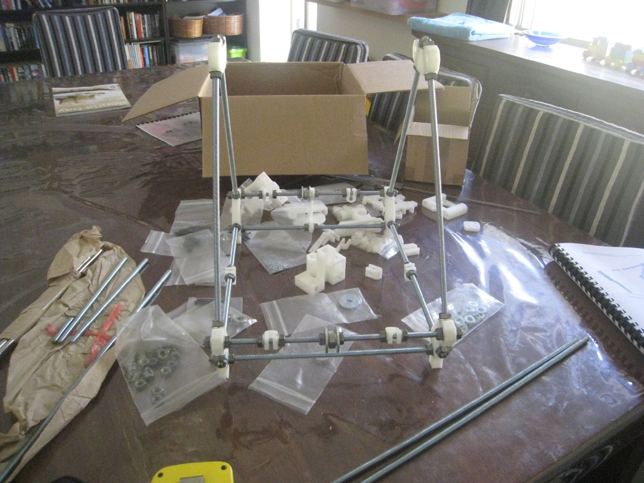
Next up, I had to level everything up, so I could properly attach the smooth Z-rods:
Levelling up the printer
Attaching Smooth rods
Not quite square yet.
Then disaster struck. My one-year-old son, Ben, knocked the X-axis parts onto the ground. When I picked it up, there was a large crack through the part!
Split!
I think that it was a combination of the drop, plus I suspect that I overtightened the retaining screws. I think that this highlights a weakness in the design, as the screws are pushing against the ‘grain’ (the printed layers) of the printed material. This can be seen in the above photo, as the part has split along a layer boundary. I suspect that it would be better to rotate the retaining screws 90 degrees, so that they push across the grain.
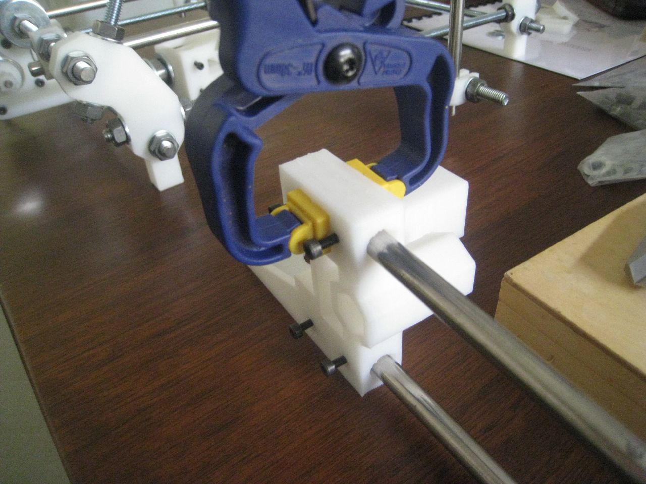
I found some glue, and put the part back together. Time will tell if this repair will last, but I think I’ll definitely move this part towards the top of the list of parts to print out once the printer’s running, just in case.
Glued part
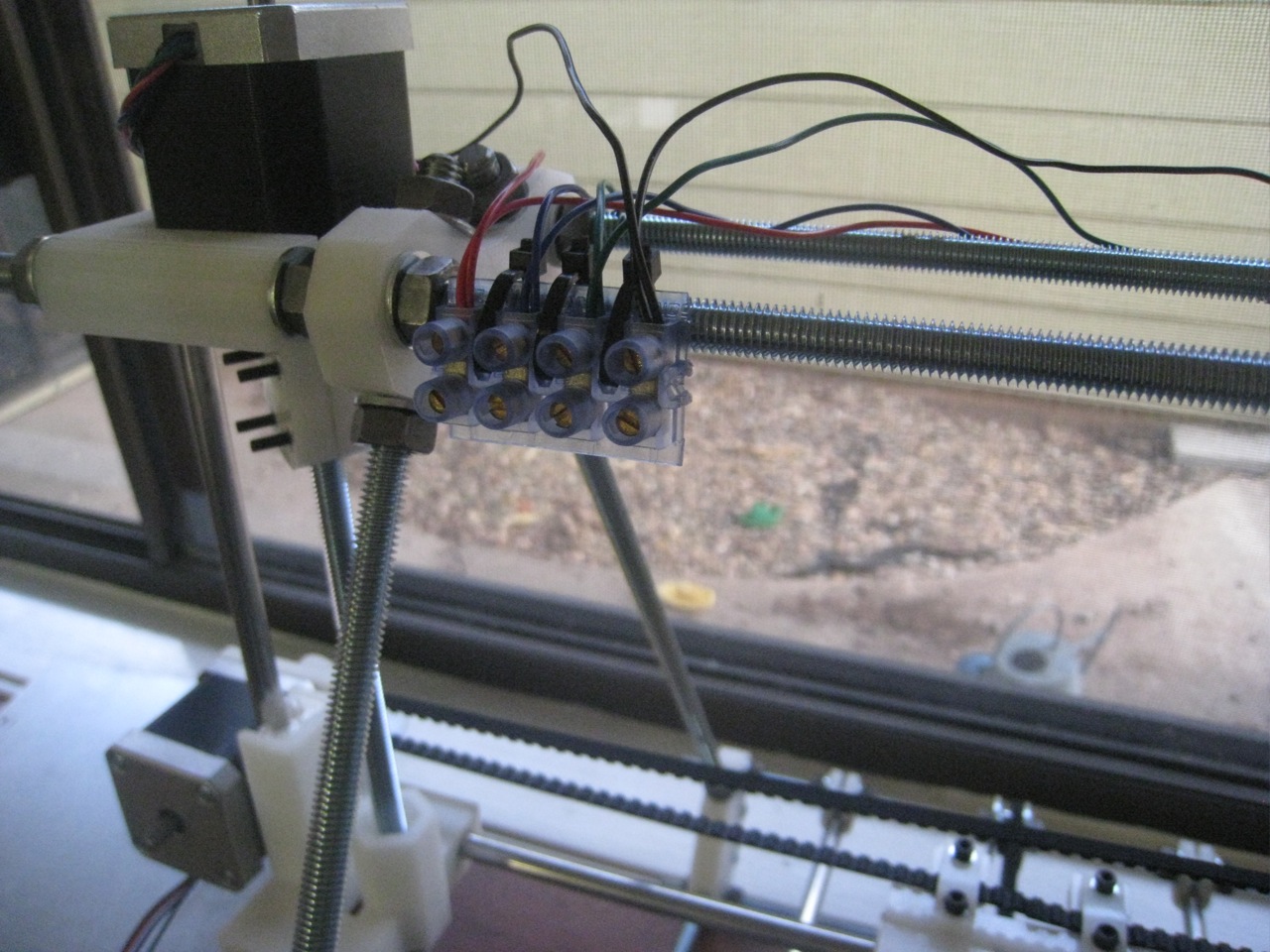
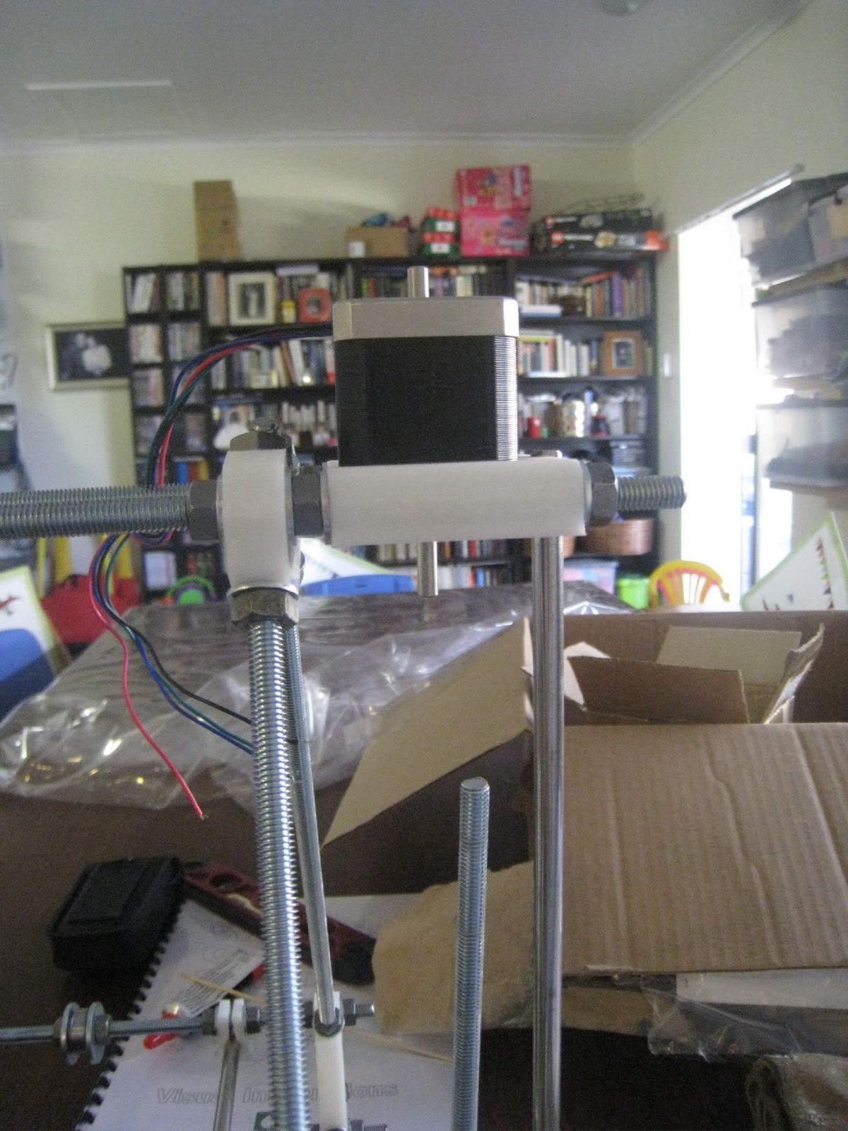
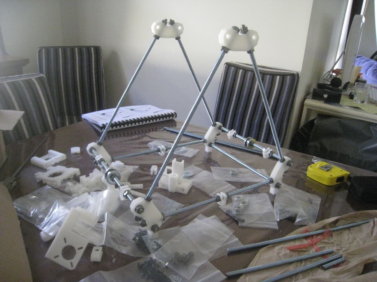
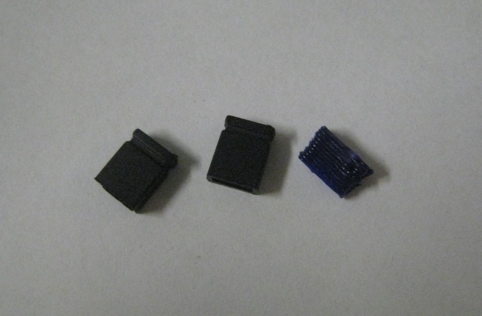
One of the nice things about using Nophead’s parts is that it’s got his Z-axis couplers by default. These look to be a much more robust solution to z-wobble.
I had a bit of trouble attaching them at first. The part looks like it’s designed for a 6mm spindle, but the motor spindle was only 5mm. A quick check of the part on Thingiverse answered it for me – the spindles need rubber sleeves over the top of them.
Nophead’s Z-couplings
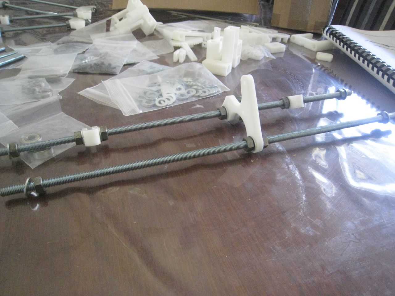
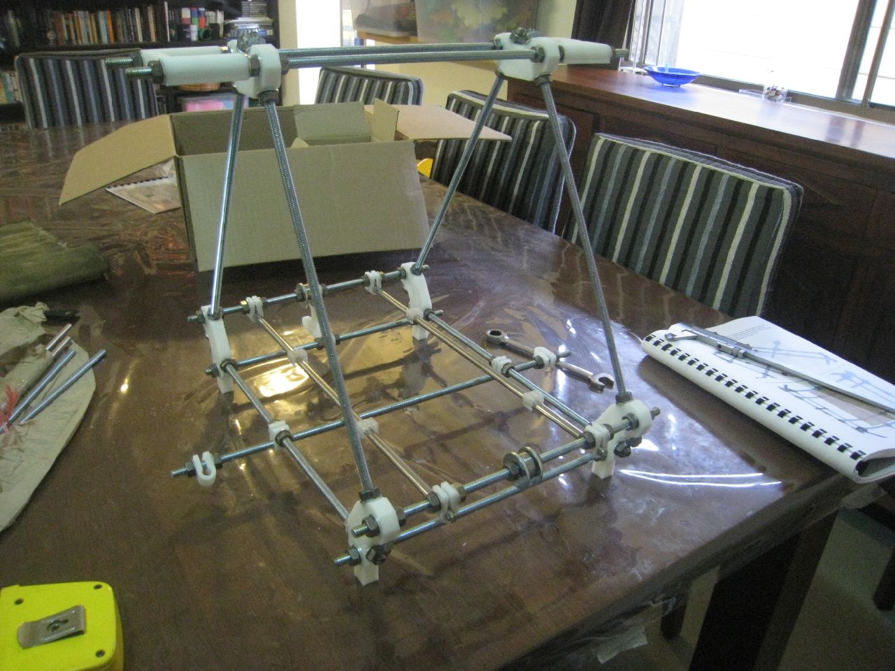
Z-Axis threaded rods
Z-Axis Motors
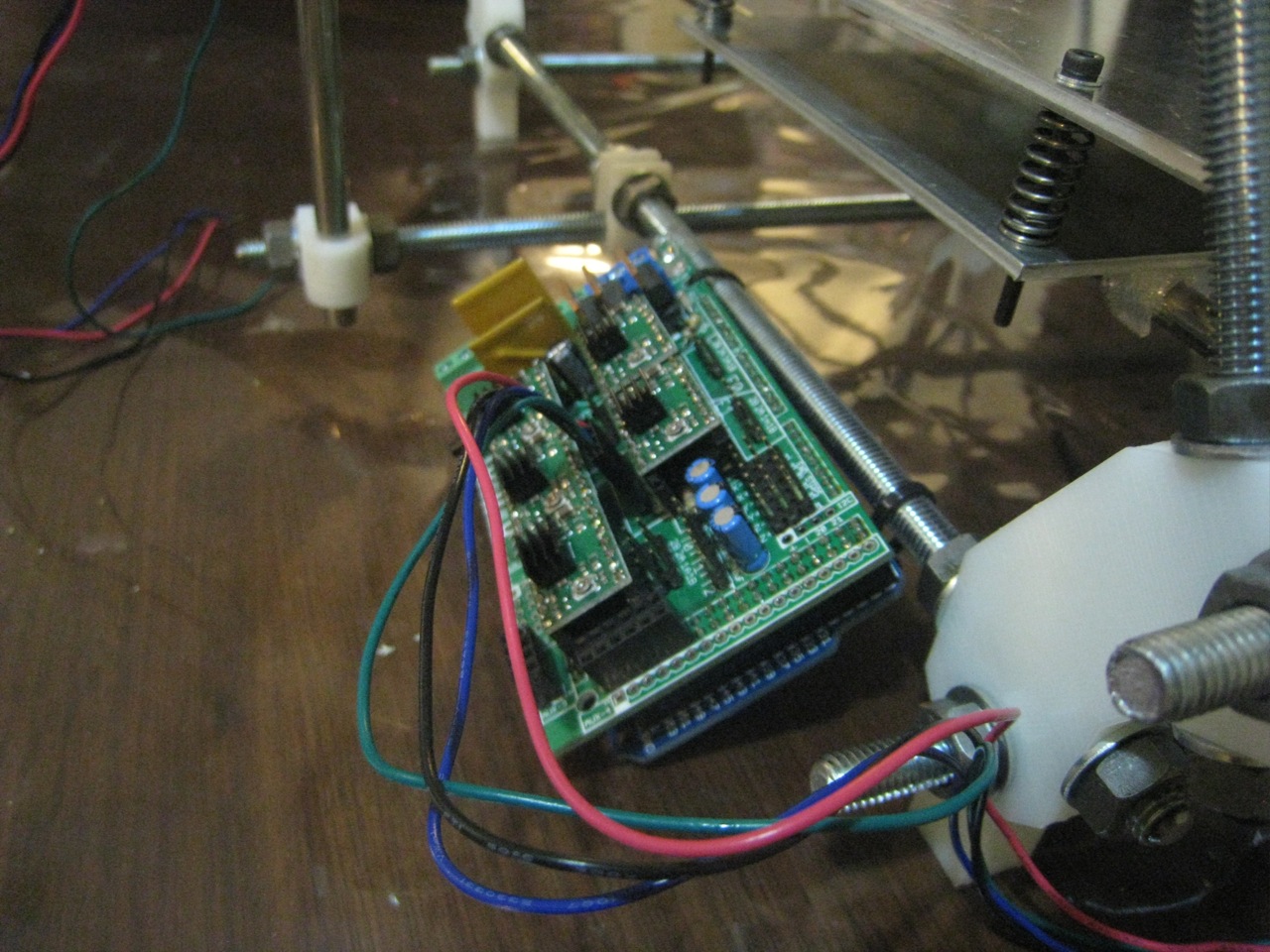
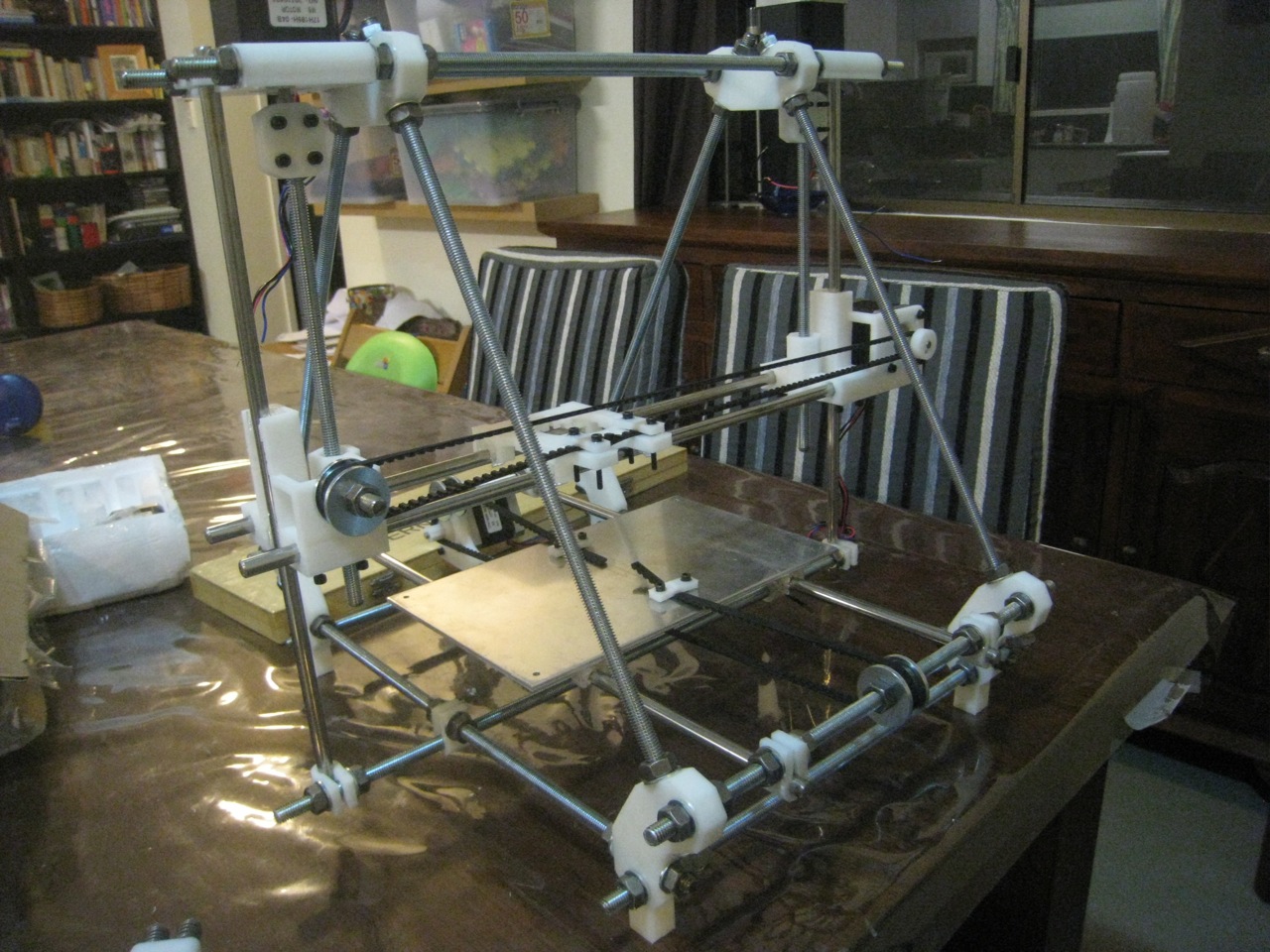
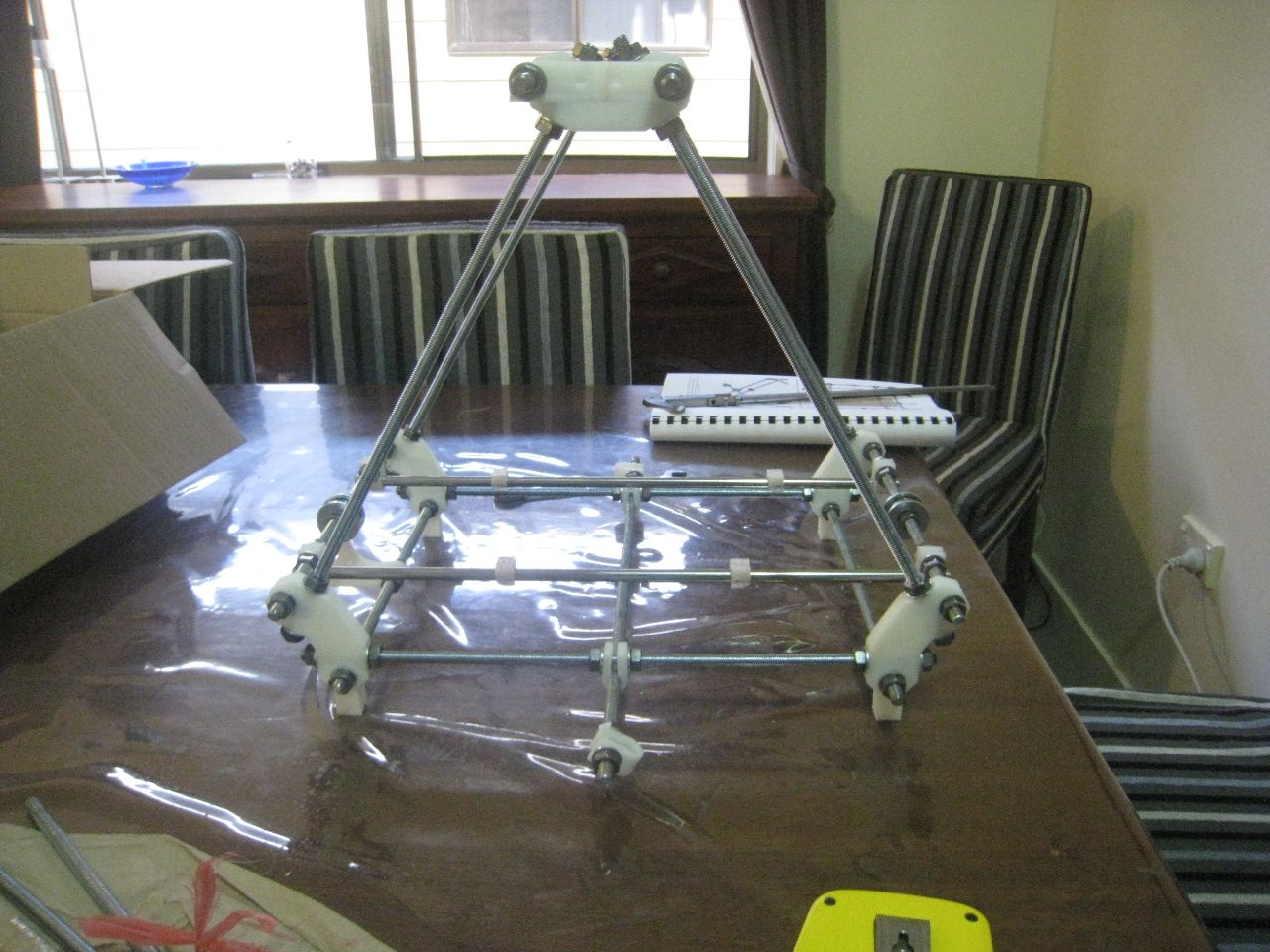
I attached the z-couplings to the motors and driving rods. That was the end of the second day’s build.
I’ve also realised that I’ve got a problem. The hot-end I’ve got (Arcol) won’t attach to Wade’s extruder. I need to get a new one printed up. I’ll hit up the Australian Forums, to see if I can get someone to help.
End of second day
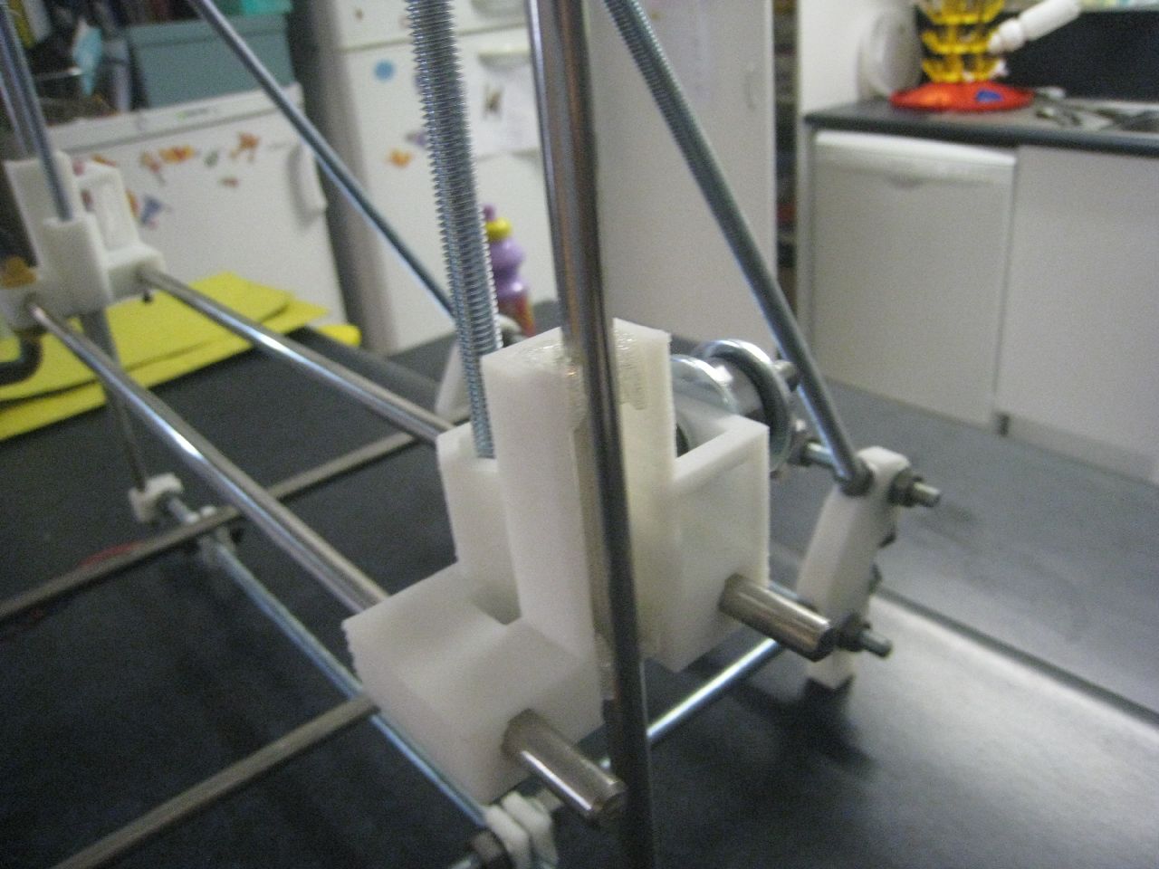
Attached Couplings
Glued Z-Axis bushings


