Tag Archives: motor

Precision Flats

Several people have recommended that having flats on your motor shafts is a good idea. After having a couple of issues with my extruder motor gear slipping, I thought that it might be a good idea, too. The suggested way of doing it is to grip your motor shaft in a vice, and then file it down.

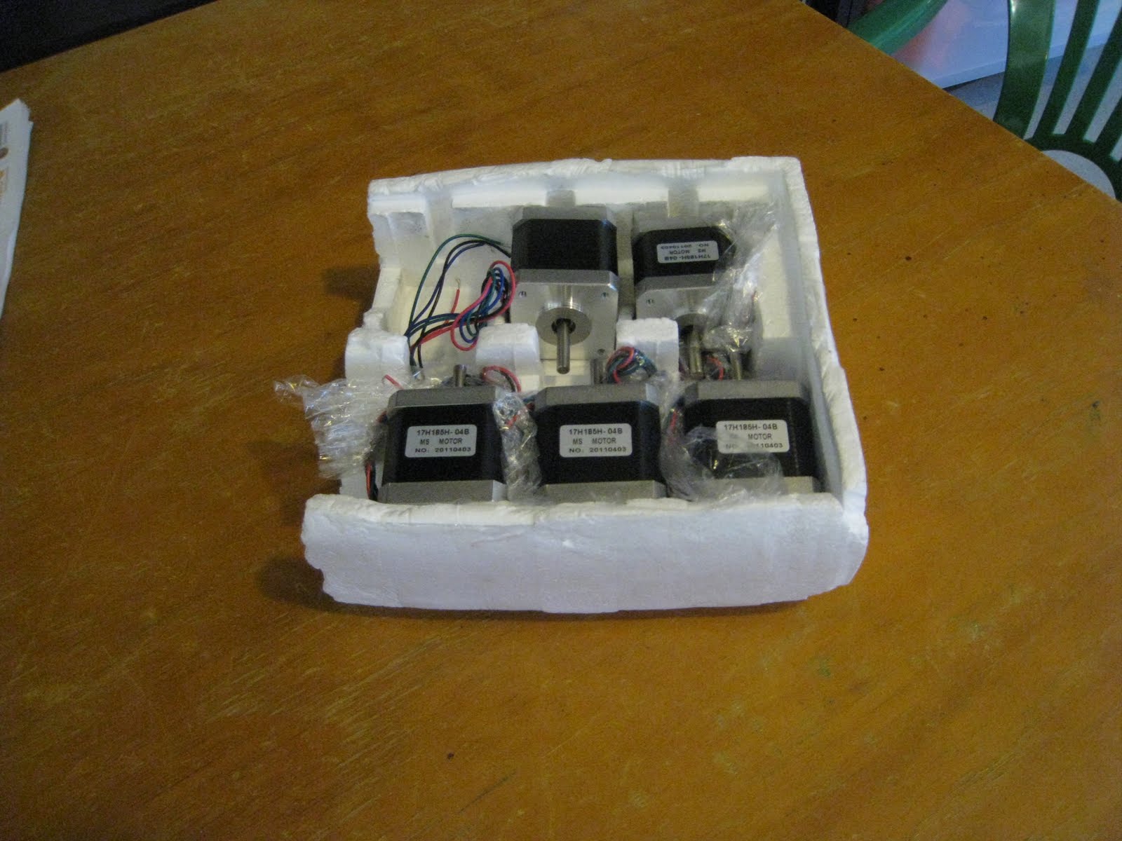
Fortunately, at my workplace, there’s a guy who’s a keen machinist. I passed the stepper motors along to him, and asked him if he could put some flats on the shafts. He thought it was a pretty easy job, and didn’t even ask for payment in beer. Here’s the results back a few days later.Stepper motor with precision flat

Now with some nice flats on the motor shafts, I thought that this would be a good time to fit the aluminium pulleys I had previously purchased. Unfortunately, the grub screws for these pulleys are far to long, they sit up into the tooth void when screwed down, causing the belt to skip over that tooth. To rectify this, I’d have to cut the screws down.

My first attempt was to cut the screw in half with a hacksaw. Unfortunately, this was a bit too much, and only left about 1mm of screw remaining. This should work in securing the pulley, but I’ll have to keep an eye on it.

For the second attempt, I just held the grub screw with a set of small pliers, and filed the end down to a shorter length. Although it was quite slow, it did the trick in getting the screw to just the right length.

Here’s the motor with the pulley attached. It looks great, and should really cut down on backlash. The belt fits in like glue.

Stepper motor with aluminium pulley

Axes Alive!

I finished wiring up the axes yesterday, so I thought I’d plug everything in and give it a test run. Just about everything worked first go!

All the endstops worked, and all the axes travelled, with the sole exception of the Y-axis, which travelled in the wrong direction. After flipping the connector around that axes was working correctly, too.

I noticed that the axes were running into their stops at the non-endstop end. I figured that the maximum travel distances were incorrect. So I measured them up accurately, then went into the firmware and made the following changes:

const int X_MAX_LENGTH = 170;
const int Y_MAX_LENGTH = 170;
const int Z_MAX_LENGTH = 88;

after which the printer then would correctly stop at these limits. I recorded a short video of the printer homing:

Once this test was done, I wired in the extruder and gave it a test, which was successful as well. I didn’t bother measuring the steps / mm for this extruder, since I’ll be changing it next week for a Greg’s Hinged Accessible Extruder.

There’s not much else I can do on the printing front until I can get the extruder and hot end sorted out, so I’ll have a look at the heated bed, try and get it set up as well.

Strong Stepper Motors


In various classes they teach you that there’s no real difference between motors and generators, it just depends on which way the current is flowing. This short video really shows that principle, as well as the strength of these little stepper motors.

I was trying to level out the X-carriage yesterday when I noticed this effect. These motors are completely mechanically separated from each other. They’re just connected electrically, through the connector block you can see in the middle of the video. Turning one of the Z-rods turns the other, with a surprisingly high degree of efficiency.

Electronica

Now that the hardware’s finished, it’s time to wire up the electronics. One annoying thing about my stepper motors is that they only have short wiring, which doesn’t allow them to reach all the way to the electronics from every location. I’ll have to extend a few wires, which will be annoying.

Z-motors connected together

First motor connected up
I tried putting the electronics in various locations, but it turned out that the bottom-left corner had the best combination of tidiness and short cable runs.

On a lean

I zip-tied the electronics to the frame, to stop them from wandering. Unfortunately, it’s on a bit of a lean.  Once the printer’s up and running, I’ll print up a tidier box to put the electronics in.

The endstops were then screwed on, and attached to the electronics as well. I just need to extend the wires for the extruder and the z-motor, hook them up, and then I’ll be all finished!

Spinning Motor, Take 2

Now armed with a full set of jumpers, I thought I’d try and re-create my motor-spinning test from a couple of weeks ago.

I carefully fitted all the jumpers to the shield (three jumpers per stepper motor for 1/16 stepping), then hooked up the power and started Pronterface.

Success! The motor is now spinning backwards and forwards. I’m now definitely all set to start assembling the printer over the weekend.

Getting a Motor To Spin

Since I’m still waiting for the hardware to arrive, I thought I’d try and hook up one of the stepper motors to the electronics, and try and get it to spin. Easy enough little task.

So I hooked up the power supply to the board, taking extreme care to make sure I get the polarity right on the cable. I then hooked up the motor to the extruder port, and then the electronics to the computer. I then put on one of the toothed gears on the motors, so that its movement would be clear.

Motor Test Setup

I then fired up pronterface using my little script, connected to the electronics, and hit ‘extrude’.

‘hmm’ went the motor, but with no movement. That seemed a little strange. I tried extruding a larger amount. Still no luck.

I went through various alternatives, plugging in a different motor, trying a different axis, even adjusting the potentiometers on the stepper motor drivers. No luck. With nothing else I could think of, I went to the reprap IRC channel, where there where many willing helpers with suggestions. Most of them suggested ideas that I had already thought of.

One IRC-er suggested that the problem was that I was missing jumpers on the RAMPS shield board. To check, I pried up the stepper motor drivers and had a look. No jumpers! With no jumpers in place, the board was trying to do full stepping, rather than 1/16th stepping.

Cursing Auzze under my breath, I shot him a quick email, letting him know that I was short 12 jumpers. He was extremely apologetic, and promised to quickly throw some in the post.

Hopefully the jumpers will fix the problem, and the motor will spin on command.

Moving bits

This week, the PSU and the stepper motors arrived.

I decided early on in speccing out the printer that I wanted to go with a heated bed. It generates much higher quality prints, but with no need of a raft. One of the problems generated by having a heated bed, however, is that you need almost 20 amps of power. Each stepper motor (or more correctly, the stepper motor driver) is rated for about 2 amps, and the heated bed can use up to 9 amps when warming up. Add on the hot end, and you’re nearly at 20 amps when starting off a print. Fortunately for power bills, this drops down a lot once the hot end and bed are up to temp.

I contemplated going route of other people and modding an desktop computer ATX supply. But in the end I decided to go for this one. It’s cheaper than a ATX supply that’s rated for 20 amps, and I don’t need the 3v and 5v outputs. This PSU is designed to recharge batteries for radio-control vehicles, but it makes a good 12v lab bench supply.

Also arrived are some stepper motors from AusXMods. The specs on these are pretty good, get the full amount of torque required (50 Ncm) at low volts and amps. These motors should easily be able to handle the load required by the Prusa.