Tag Archives: build

Final Assembly, and First Print

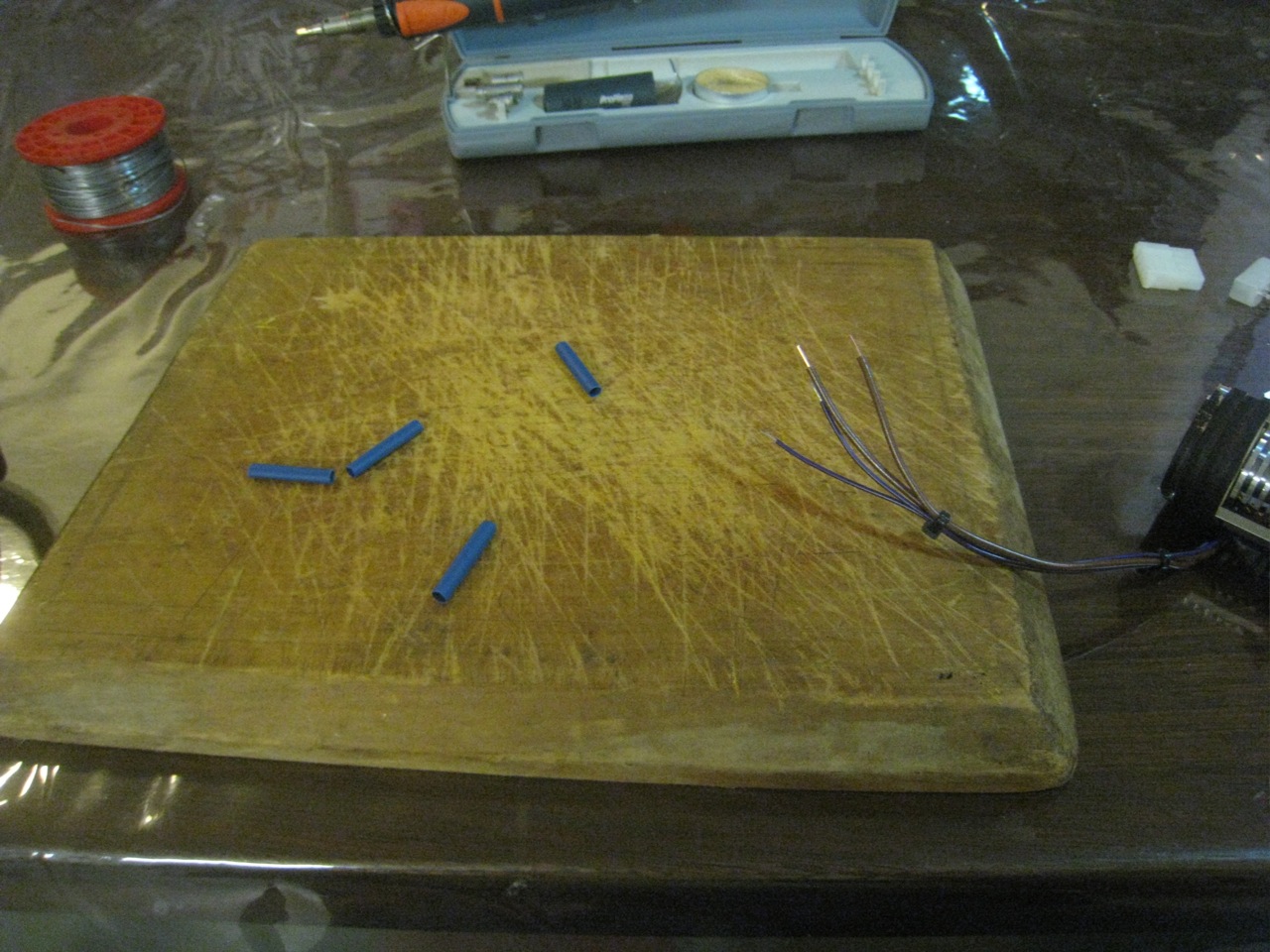
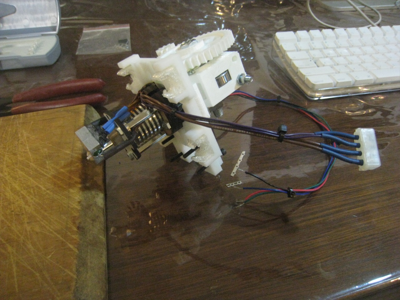
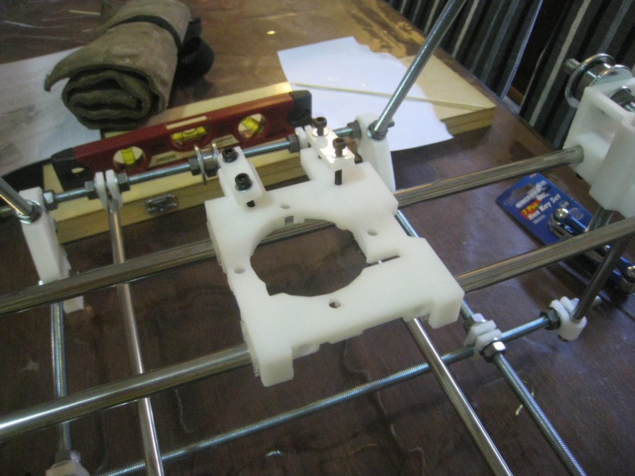
With the extruder completed, the only job remaining is to hook up the extruder motor and the hot end to the electronics. The new wire-stripper made that a much easier job.

Connecting up the hot-end

 Molex connector for easy removal
One the extruder and hot end was complete, I removed the hot end, so that I could do some extrusion calibration. Whilst some default values for Wade’s extruder are known, Greg hasn’t provided any starting values for his extruder. I started out by doing some 50mm extrusions, and calibrating using Prusa’s calculator. Once that was done, I reconnected up the hot end, and put everything together. The printer was complete!

  Finally complete

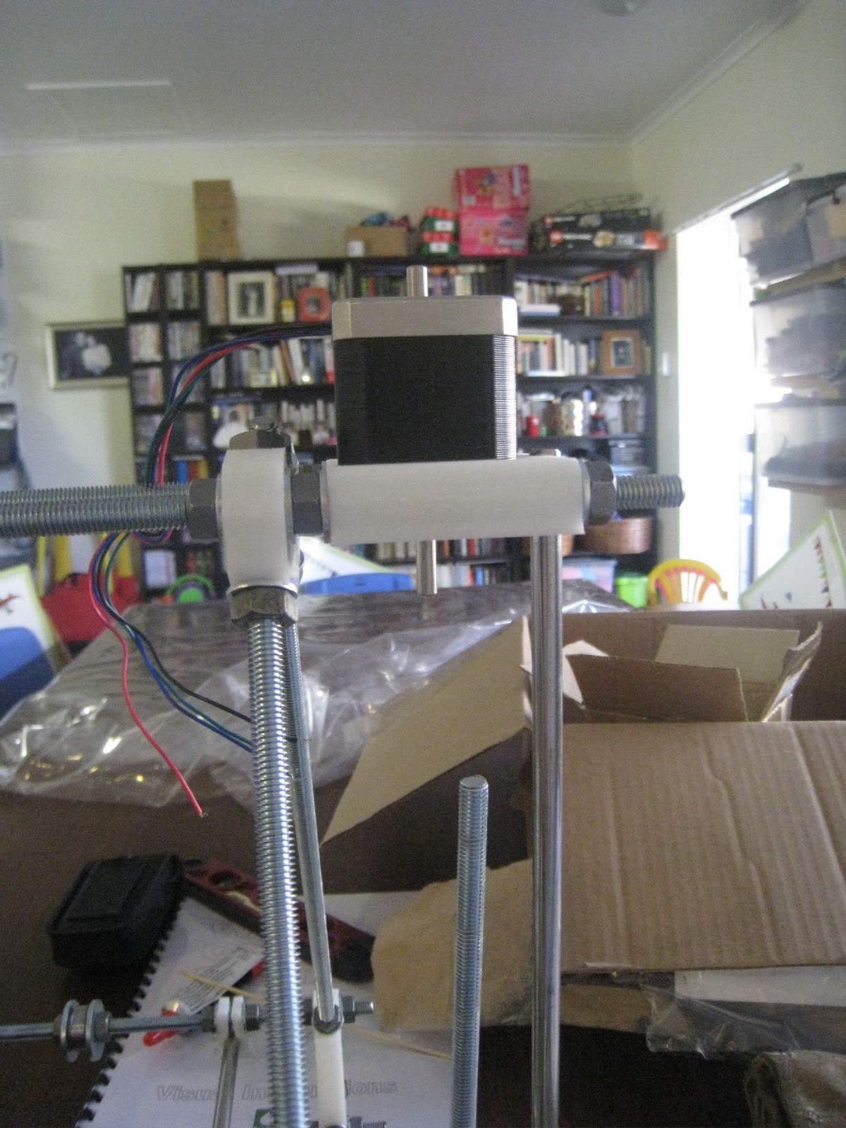
I started off by doing a few extrusion tests. They went well to start with, with the hot-end warming up, and spitting out a line of filament. I then tried to set the Z-value of the tip. Then the printer started acting strange. The Z-motors were going crazy, not spinning enough. Spinning up, then down. I couldn’t figure it out. I went to the IRC channel, but no-one was interested in helping today.

Not sure what else to do, I started fiddling with the Z-connector on the board. Sure enough, with some fiddling, the Z-motors would either work perfectly, or not at all. I took the connector off, to have a look, and discovered that one of the wires had broken inside its sheath. The intermittent connection of the wire was causing the erratic behaviour. I cut the last couple of centimetres of the cable, re-stripped and re-connected them.

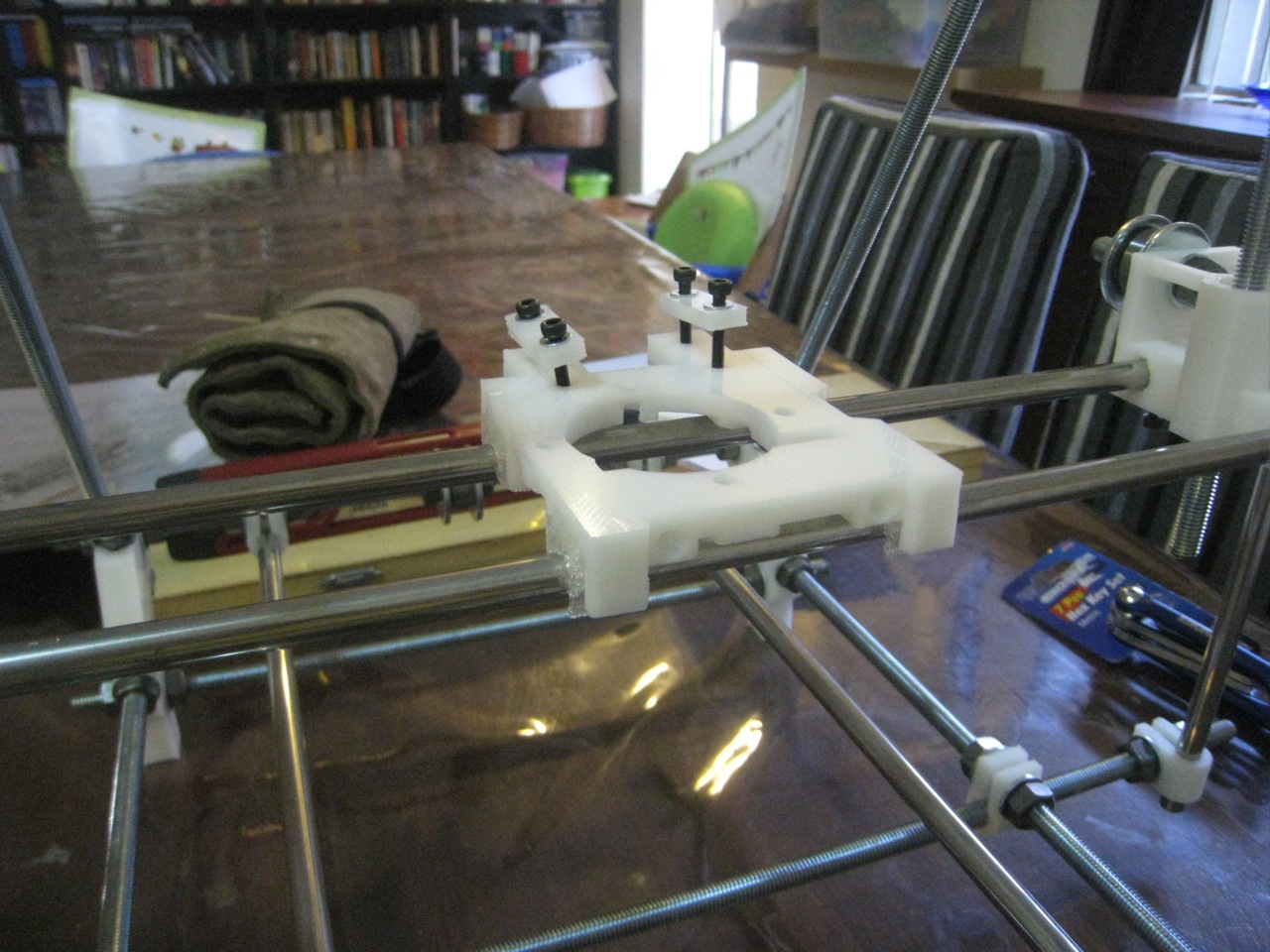
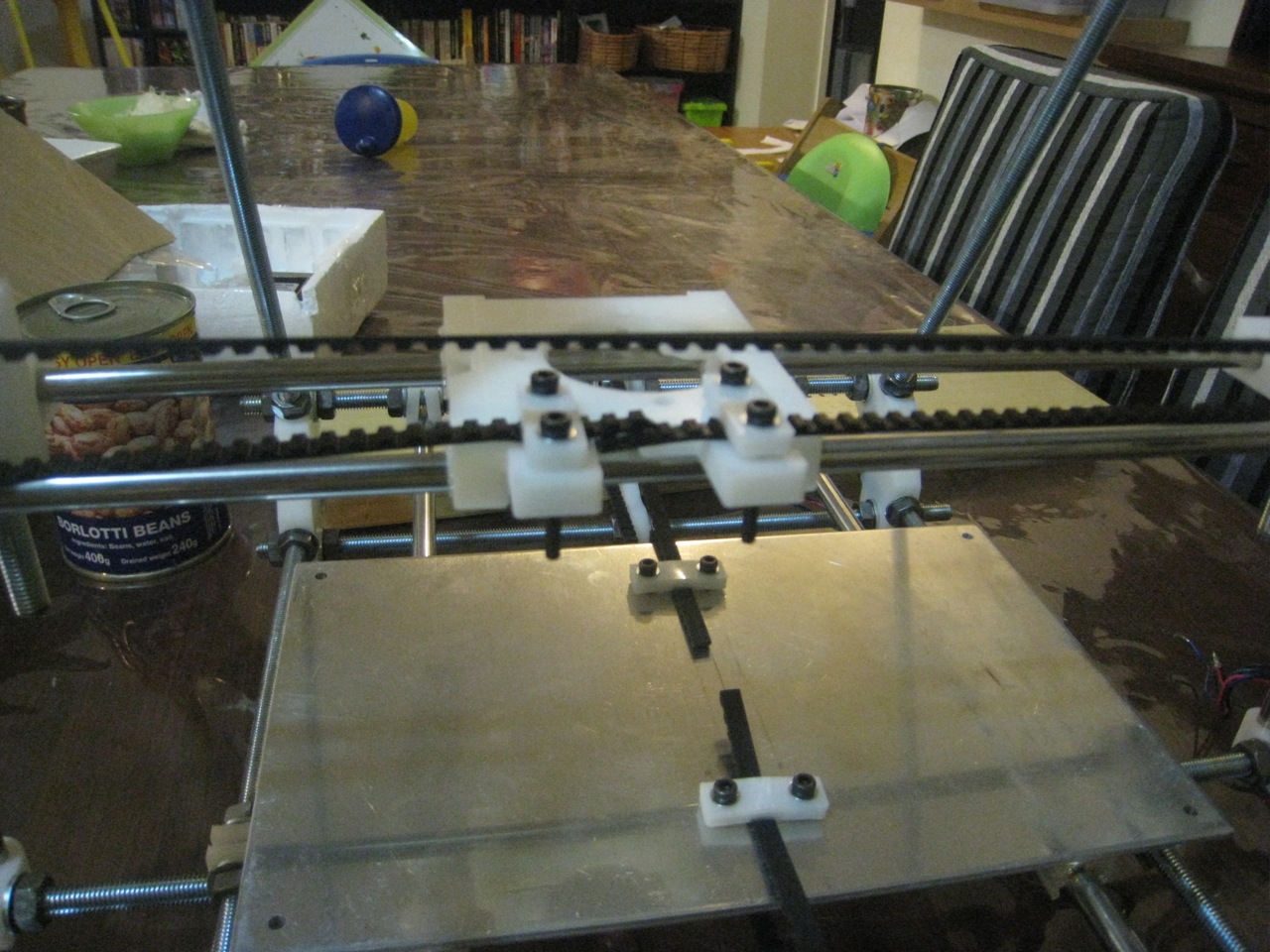
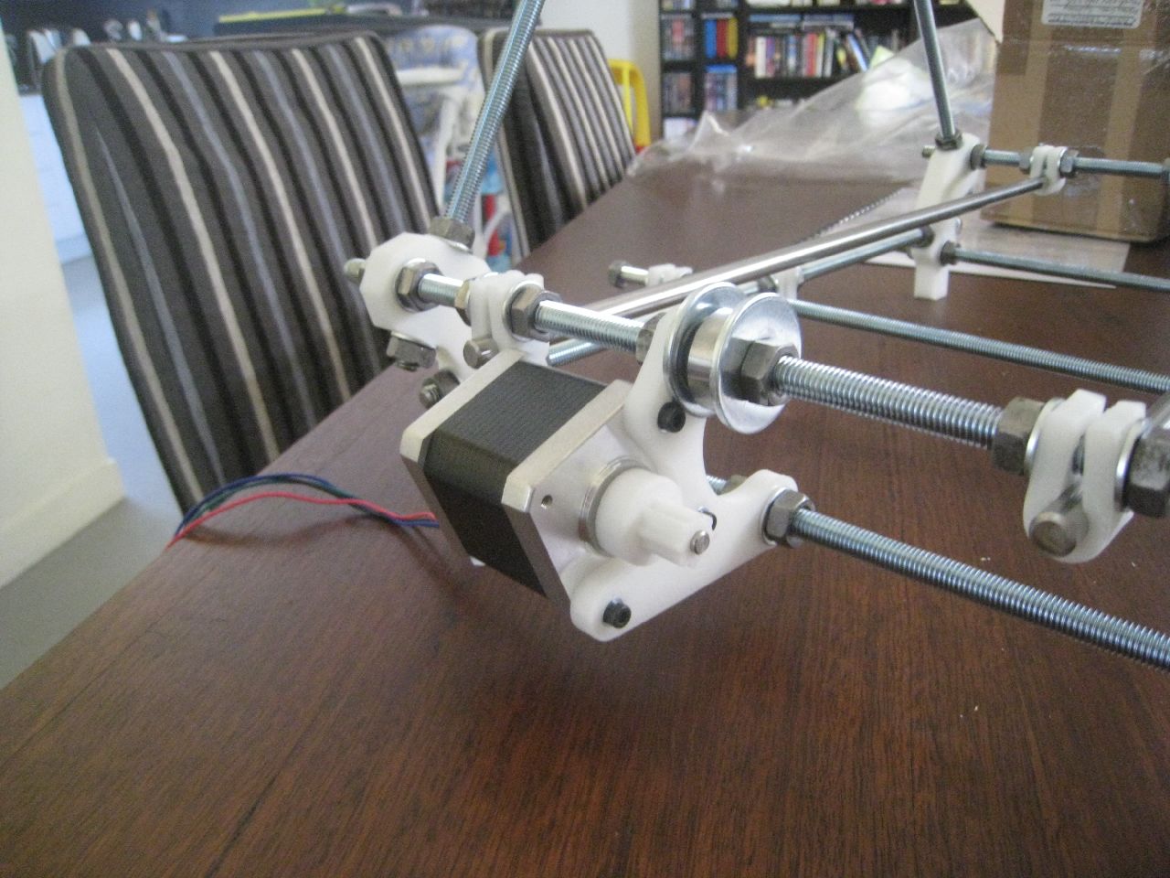
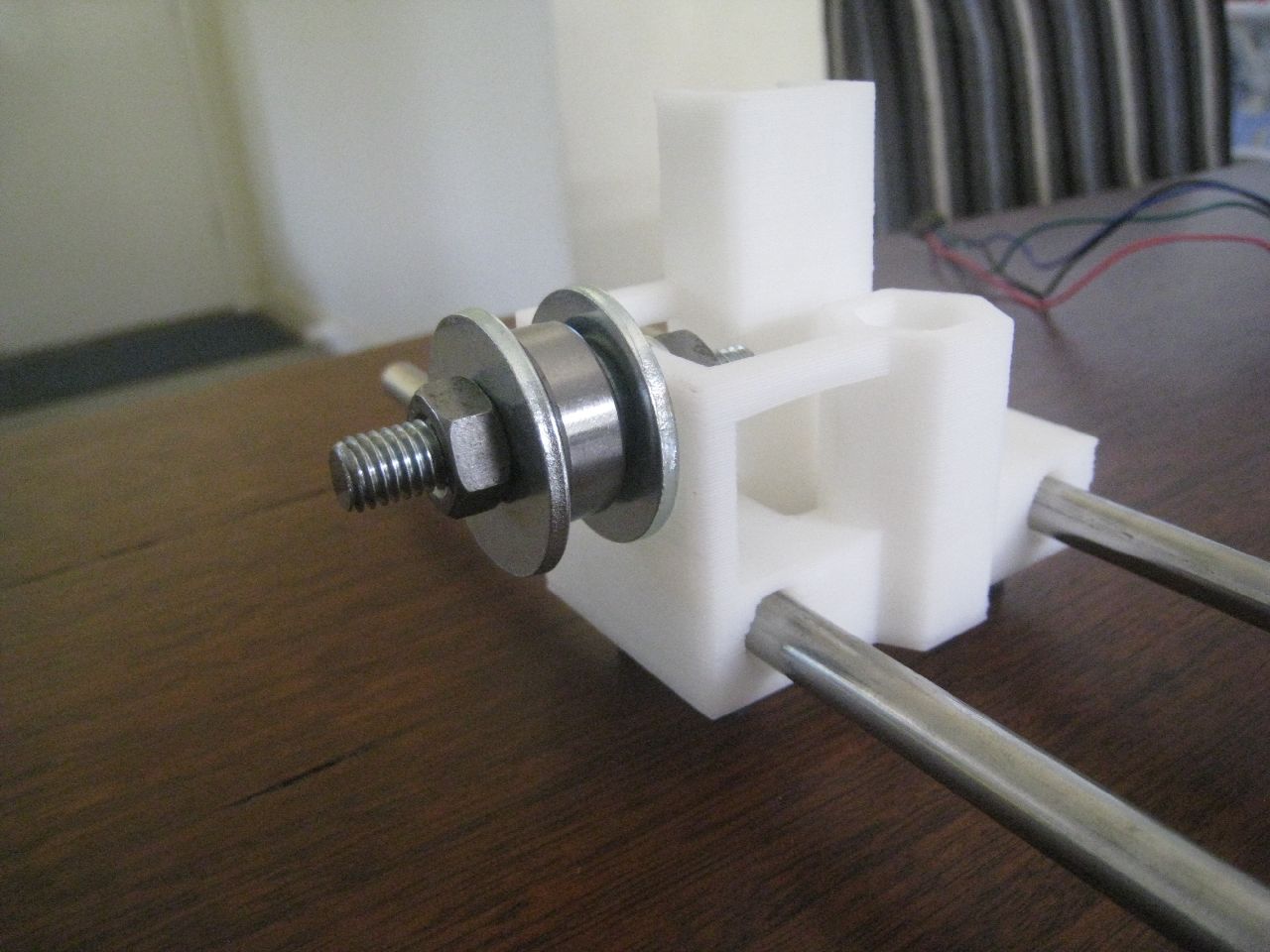
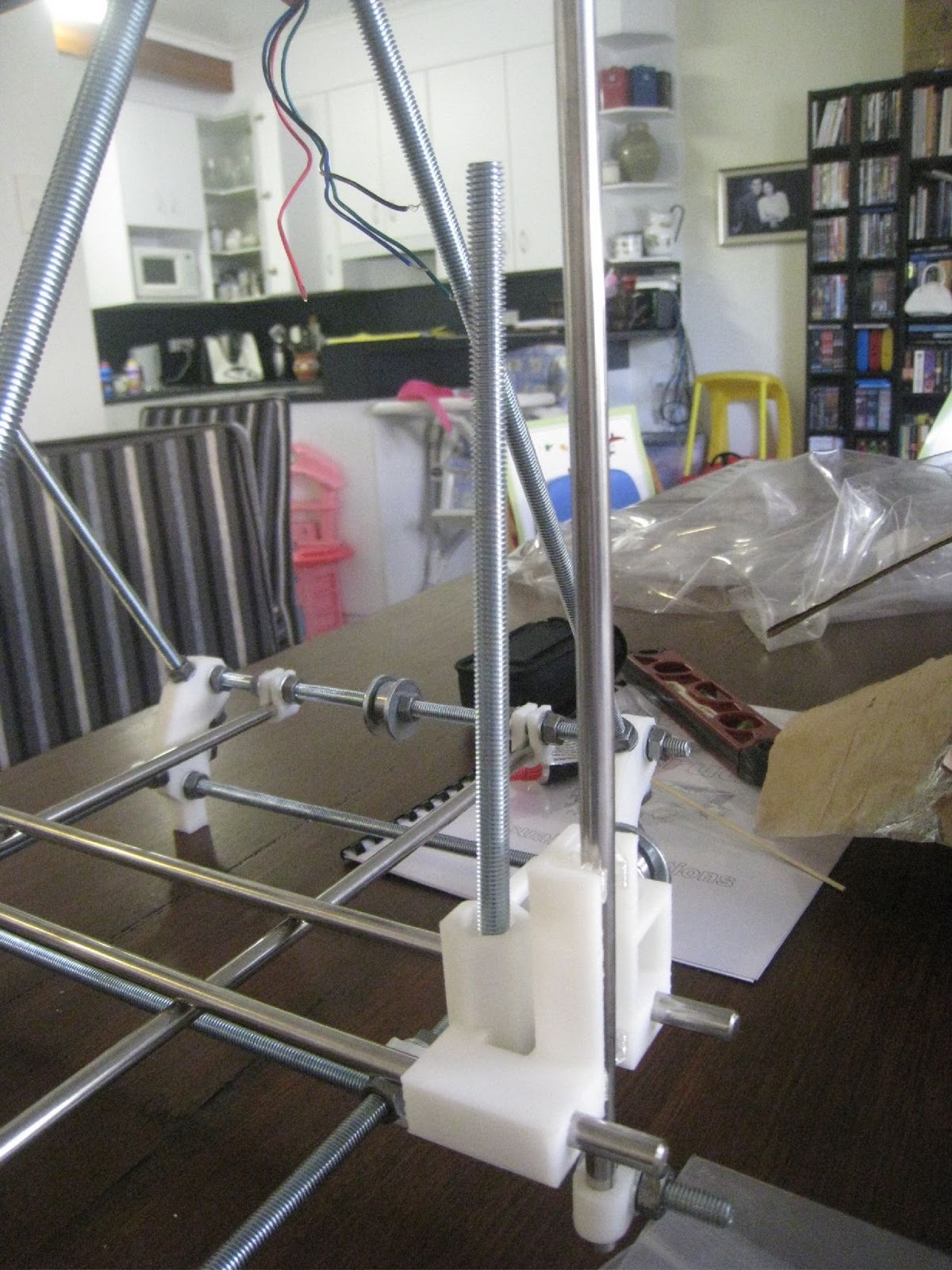
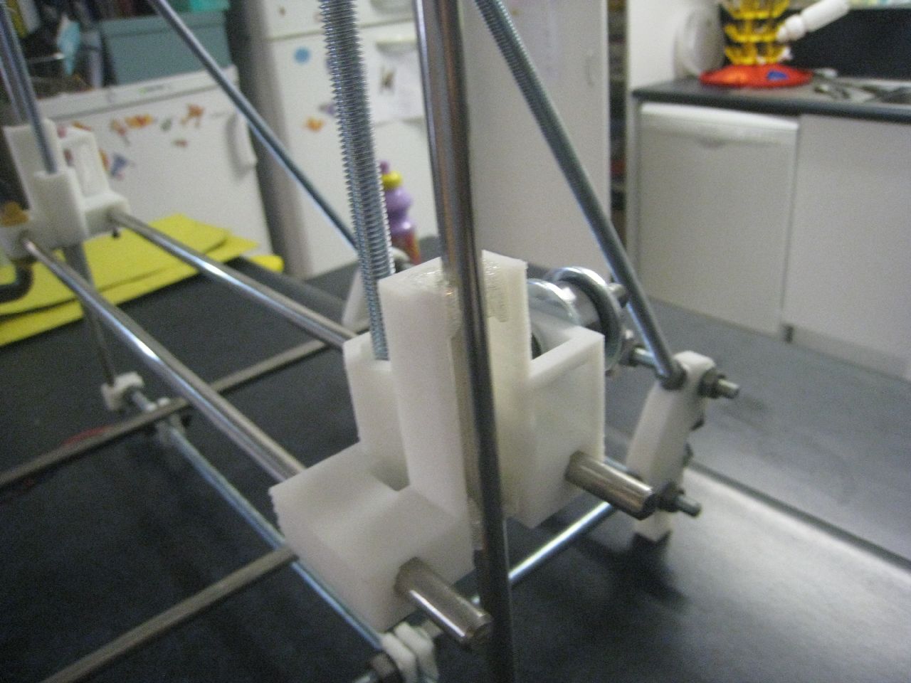
The Z-nuts also kept falling out of the bottom of the Z-carriages whenever the printer was supposed to descend. I think that the problem is that the bushings are a bit too stiff, and the Z-carriages aren’t sliding smoothly along the track. To solve this problem, I glued the nuts in place, to make it easier for the carriages to come for the ride. Travelling upward’s isn’t as smooth as I would like, either. I think I’ll put a little bit of lithium grease on the Z-rods, to smooth out the travel there.

Once those issues were fixed, I tried doing a print, starting off with the standard Reprap minimug. However, I ran into more issues right away.

Extrusion Test

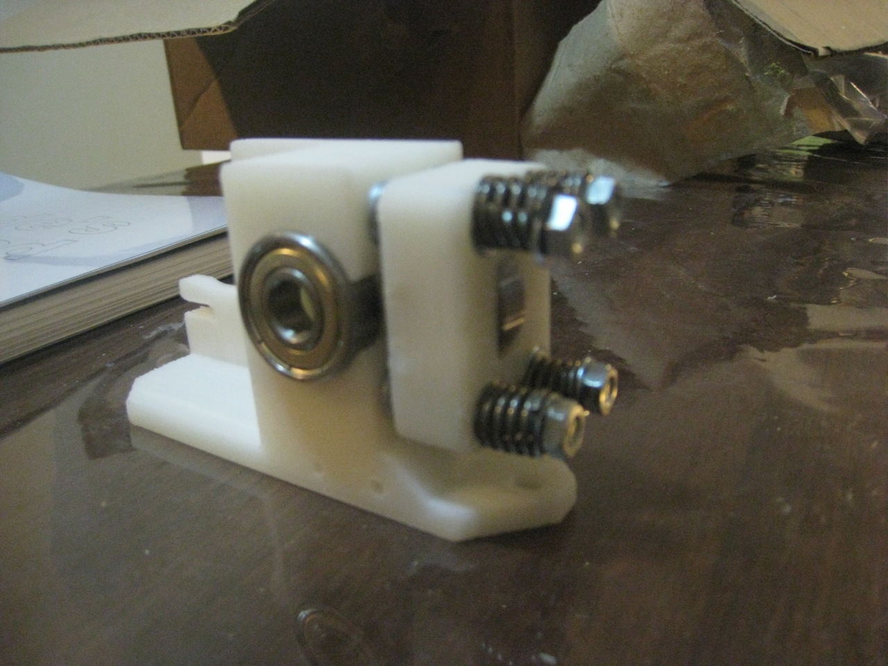
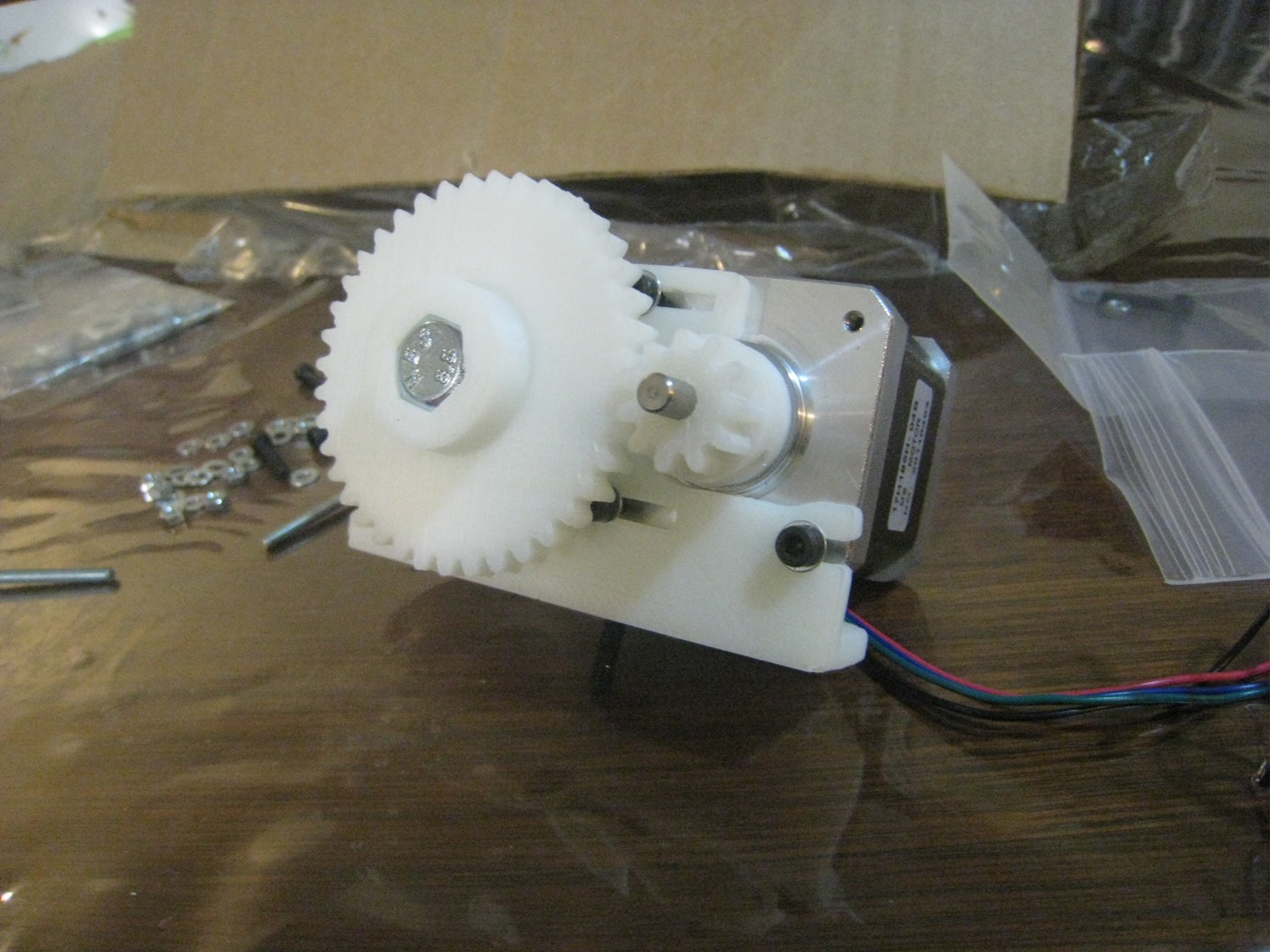
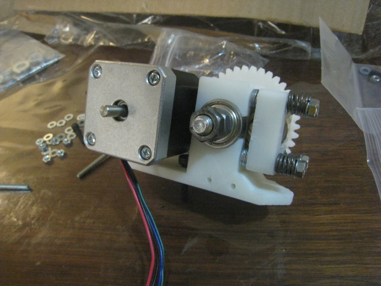
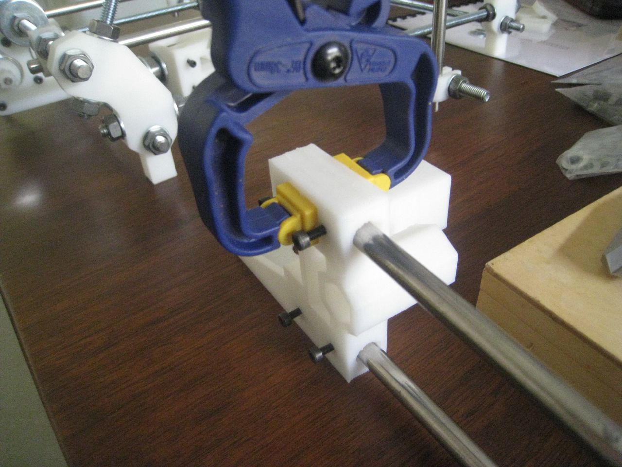
The extruder was frequently locking up. It would only turn for a few seconds before it would stop. Having a look at it, I found out what the problem was. With Wade’s design, the extruder turns so that it has the effect of loosing up the nut on the far side of the extruder. This is compensated for by using two nuts. Greg’s has the opposite problem. Because it turns in the opposite direction to Wade’s design, it tightens up the nuts. It keeps on doing this until the extruder binds up from the force of the nut.

I got around this problem by taking off the standard nuts, and replacing it with a Nylock nut that a lot less prone to movement. Hopefully, this will fix the problem. I then tried to print the minimug again. To increase the chance of success, I decided to add in a raft in the Sfact settings. The print started off badly, with the tip dragging through the kapton tape on the heatbed, due to being too low in some places, but then went to the centre of the print bed, and started printing at just the right height.

The raft went down perfectly, with sharp lines, and stacking nicely. However, after that, things starting going downhill. It started to print some of the minimug off the raft. It kept printing, but it was messy, as strands were just loosely dropped on top of each other.

At least the raft looks good

After a while the extruder stopped extruding properly, it was hardly outputting any filament at all. At this point I stopped the print, as it was failing badly. I then had a look at the extruder, to try and nail down this problem. It puzzled me for a little while until I realised that the small gear was turning freely on the motor shaft. I tightend up the grub screw. Hopefully, it’ll work for a while. I intend to file some flats on the motors, but unfortunately, our machinist at work has broken his hand, making it hard for me to use his help.

My main problem is that the heatbed just isn’t flat, and when it’s not flat, then you can’t get the tip close enough to the bed. I also don’t like trying to set the Z-stop when the tip is so close to the bed. It takes quite a few tries to get it so that it’s ‘just right’. I’m tempted to inverse the Z-stop, set it as an upper limit, then use the software to set the lower limit of travel. That would probably work particularly well with using Nophead’s idea of the magnetic calibrator.

 Minimug. Theoretically, anyway.

I was going to take the heatbed off, and just print on the upper steel bed, but my wife Cathy suggested that I could use one of her glass trivets. Given that it’s designed to be used as a trivet, it should be made of Pyrex. In any case, she wasn’t stressed if I broke it, as she doesn’t like it.

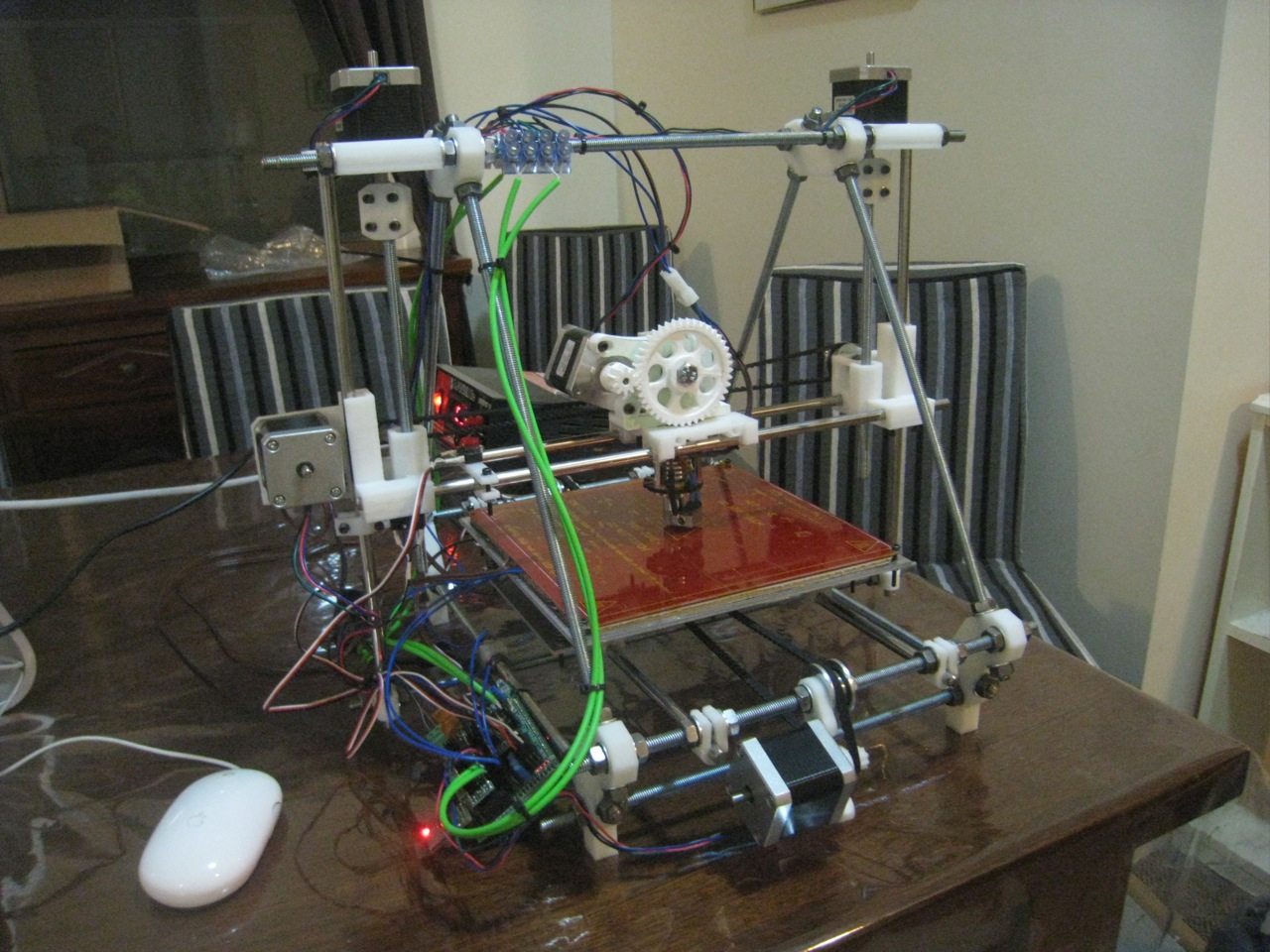
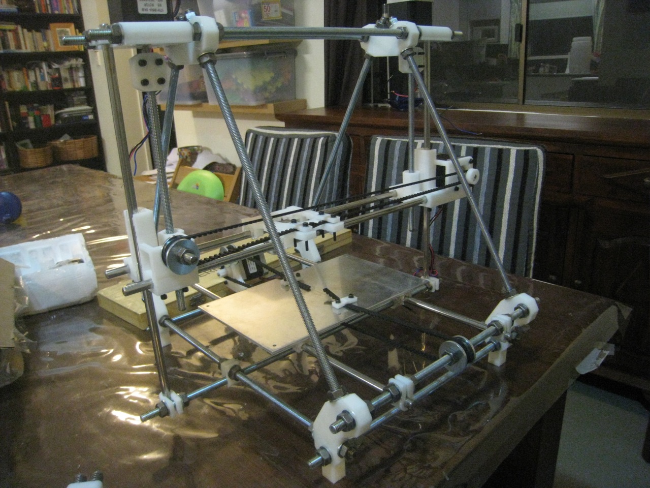
So after a lot of work, and a lot of problems encountered, I finally got the printer to print – something. Hopefully, I’m over the hump for the physical issues, and I can just tackle calibration for now. I think for tonight’s print, I put the minimug on the back-burner, and do a calibration cube, see how that turns out.

Axes Alive!

I finished wiring up the axes yesterday, so I thought I’d plug everything in and give it a test run. Just about everything worked first go!

All the endstops worked, and all the axes travelled, with the sole exception of the Y-axis, which travelled in the wrong direction. After flipping the connector around that axes was working correctly, too.

I noticed that the axes were running into their stops at the non-endstop end. I figured that the maximum travel distances were incorrect. So I measured them up accurately, then went into the firmware and made the following changes:

const int X_MAX_LENGTH = 170;
const int Y_MAX_LENGTH = 170;
const int Z_MAX_LENGTH = 88;

after which the printer then would correctly stop at these limits. I recorded a short video of the printer homing:

Once this test was done, I wired in the extruder and gave it a test, which was successful as well. I didn’t bother measuring the steps / mm for this extruder, since I’ll be changing it next week for a Greg’s Hinged Accessible Extruder.

There’s not much else I can do on the printing front until I can get the extruder and hot end sorted out, so I’ll have a look at the heated bed, try and get it set up as well.

Assembling, Stage Three

Continuing on with my build. First up is attaching the X-carriage, and gluing it to the bushings.

X-Axis Attached

Sliding Smoothly

I went to the hardware store this afternoon, and picked myself up some 3.2mm drill bits. With this in hand, I was able to drill the holes I needed to in the base plate, and then attach it to the printer.

Y-Axis Belt attached

X-Axis Belt
Printer with all Axes finished

Next up on the list is to assemble the extruder. I don’t really need to do this step, since I’ll be replacing the extruder base with one that’s compatible with the Arcol extruder, but I thought I’d do it anyway, get the experience, and try and various running experiments without the hot end or filament.

First Pieces in Place

Springs fitted
Finished Extruder – Front

Finished Extruder – Rear

And that’s all the hardware complete! Next up will be to wire everything up.

Assembling, Stage Two

After spending overnight drying out, the bushings were well attached to the base, and were sliding smoothly up and down the rods.

As I mentioned in my previous post, I’m a bit stuck on a couple of small points, particularly the holes I need to drill in the base-plate, but I’ll keep pushing ahead. First up for today, after measuring up the base-plate, is to attach the Y-motor, and make sure that it’s all square. Due to the lack of  a 1mm allen key, I can’t attach the aluminum gears that I bought, so I’m just affixing the printed ones for now. I can definitely see the advantage in the machined gears. I have to pull the belt pretty tight to stop it from skipping over the (not perfectly sharp) gears.

Attached Y-motor

After the motor was attached, I started to work on the X-axis. This is dead simple. 

X-Axis parts

The quality of Nophead’s parts really is fantastic:

Once the X-axis was built, I set it aside on a spare chair.

Next up, I had to level everything up, so I could properly attach the smooth Z-rods:

Levelling up the printer

Attaching Smooth rods

Not quite square yet.

Then disaster struck. My one-year-old son, Ben, knocked the X-axis parts onto the ground. When I picked it up, there was a large crack through the part!

 Split!

I think that it was a combination of the drop, plus I suspect that I overtightened the retaining screws. I think that this highlights a weakness in the design, as the screws are pushing against the ‘grain’ (the printed layers) of the printed material. This can be seen in the above photo, as the part has split along a layer boundary. I suspect that it would be better to rotate the retaining screws 90 degrees, so that they push across the grain.

I found some glue, and put the part back together. Time will tell if this repair will last, but I think I’ll definitely move this part towards the top of the list of parts to print out once the printer’s running, just in case.

Glued part
One of the nice things about using Nophead’s parts is that it’s got his Z-axis couplers by default. These look to be a much more robust solution to z-wobble.
I had a bit of trouble attaching them at first. The part looks like it’s designed for a 6mm spindle, but the motor spindle was only 5mm. A quick check of the part on Thingiverse answered it for me – the spindles need rubber sleeves over the top of them.

Nophead’s Z-couplings

Z-Axis threaded rods

 Z-Axis Motors

I attached the z-couplings to the motors and driving rods. That was the end of the second day’s build.

I’ve also realised that I’ve got a problem. The hot-end I’ve got (Arcol) won’t attach to Wade’s extruder. I need to get a new one printed up. I’ll hit up the Australian Forums, to see if I can get someone to help.

End of second day

Attached Couplings

Glued Z-Axis bushings

A Bit Stuck

Argh. I’m trying to move onto the next stage of construction, but I’ve got a small problem. The next stage involves drilling two 3mm holes in the base-plate to attach the toothed belt, but both my 3mm drill bits are broken.

In addition, I need a 1mm hex key to tighten the grub screw holding the toothed gear to the y-motor. However, the smallest hex key I’ve got is a 2.5mm. Fortunately, I’ve been able to get around this one through the use of a T6 Torx screwdriver.

Time to go non-linear, and build out of sequence.

Assembling, Stage One

Time to start construction! First up is to construct the side A-frames. Everything started off well.

First frame-base

Slightly messy work-bench (aka kitchen table)

First A-frame assembled

Second A-frame assembled

Next up was to build the front and rear threaded rods.

Front Threaded Rods

The front rods assembled fine. Then in was time to assemble the rear rods here I ran into some small troubles. I only had one rod left! Checking the prusa-build website, I soon found my problem. I was using the 440mm threaded rods instead of the 294mm threaded rods. The Visual Instructions I was using don’t specify which rods you need at this stage, so I just grabbed the ones that I thought were right.

So I made myself a mental note: submit a bug report to Visual Instructions to specify which threaded rod you need. I was quite annoying (and slow) to have to unthread all the nuts off the rods, then thread them onto the correct rods.

Front and Rear rods in place

Front and Rear rods in place 

Next up is to assemble the top threaded rods. I made sure to grab the right length this time! These were pretty easy to assemble
 

 Top Threaded Rods

After the top rods are in, it’s back to the bottom, to put in the Y-Axis rods and the lower z-bar holders

 Lower Bars in Place

Lower Bars in Place

Once the Y-Axis smooth rods were in place, I spent a fair amount of time (as recommended in the instructions) making sure that the rods were parallel, both to themselves and the frame. The PLA bushing were then attached

The last stage for today will be to glue the base-plate onto the Y bushings. I’ll let that dry overnight, and resume tomorrow.