Tag Archives: extruder

A Helping Hand

A few days ago ‘Schulz’ made a post on the Australian forums. He was looking to buy a modified Wade’s Extruder that would fit on the Arcol hot-end. Those who’ve read through this blog think that this story sounds quite familiar.

So, taking pity on a fellow sufferer, I offered to print him up a Greg’s accessible extruder for him for free.

First thing up was to find the STL files. Looking at the parts posted on Thingiverse, it looked like the STL files posted there weren’t pre-compiled for the Arcol hotend mount.

I get around that limitation, I downloaded the OpenScad file also published along with it. Opening up the file it looked good, but wouldn’t compile without a bunch of warnings. It was missing some configuration files that were meant to go along with it.

At first I tried having a look at Thingiverse, to see if the missing configuration files could be found there. Unfortunately not. I then had a revelation. I went to Github, and did a search for Greg Frost. There he had his fork of the Prusa files there. Looking in the list, I saw a newer version of the extruder file, and all the configuration files that it was looking for.

Once I had all the right configuration files, the extruder compiled just fine. I then added in the options for the groovemount, and the Arcol hot-end. For some reason, the groovemount option didn’t compile in correctly, but the Arcol mount did, which is all that I was looking for.

I then exported the file to an STL, and loaded it up in Pronterface. The estimation came up as three hours, fifty minutes. Three hours later, the print finished.

What struck me during the print was all the solid layers. I only used my standard 35% fill, but it printed with a lot more solid layers. It must be a feature of Greg’s design to include lots of solid reinforcing layers.

In all, I was pretty happy with the print. It doesn’t look quite as good as Greg’s extruder that’s on my machine, but it’s relatively close. Interestingly, mine required less cleanup than Greg’s did, but his surface finish is superior.

Printing out the object gave me a great sense of admiration for Greg’s design. It’s by far the most complex print I’ve ever done. Whilst the snowflake’s were complex, they were only complex in a two-dimensional manner, and were just a extrusion of that two-dimensional shape. The extruder is a true 3-D shape of high complexity.

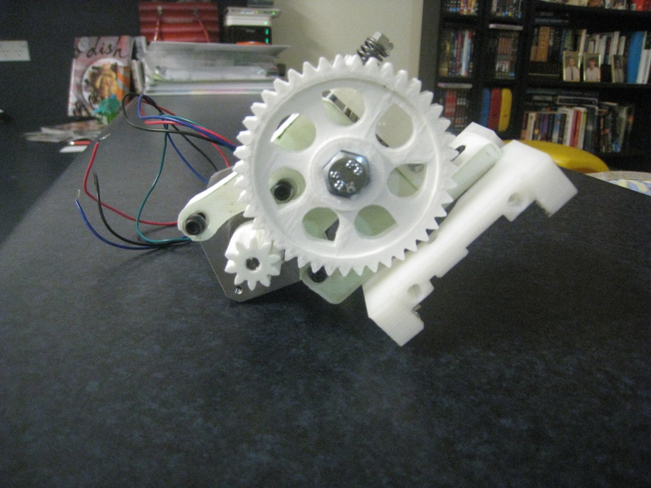
After I did the extruder, I went to do the gears. I didn’t want to print out the standard gears, so I found some STL files for some herringbone gears. The herringbone gears mesh together more tightly, so there’s less backlash from the extruder. Also, even though they are a more complex shape, I think that they’re more forgiving for poor printing.

The gears printed out fairly well. My main concern for the print was that the top of the small gear would get too mushy from too small a print area. To get around that, I put in some ‘orbit’ around the print. Unfortunately, I forgot how oozy my hot-end is. It meant that there was a lot of fine strings all around the print that needed to be cleaned up at the end.

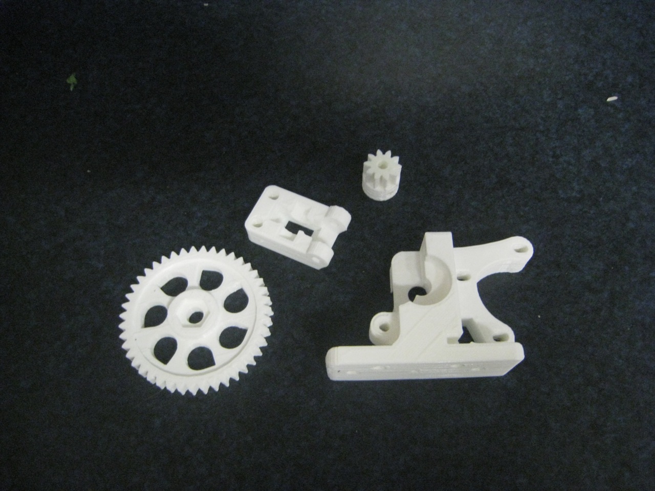
The teeth on the large gear printed fairly well. The teeth on the small gears not so well. They were a bit blobby, and needed some cleanup. They tidied up pretty well, and I think that they’ll work fine. They seemed to mesh together nicely.

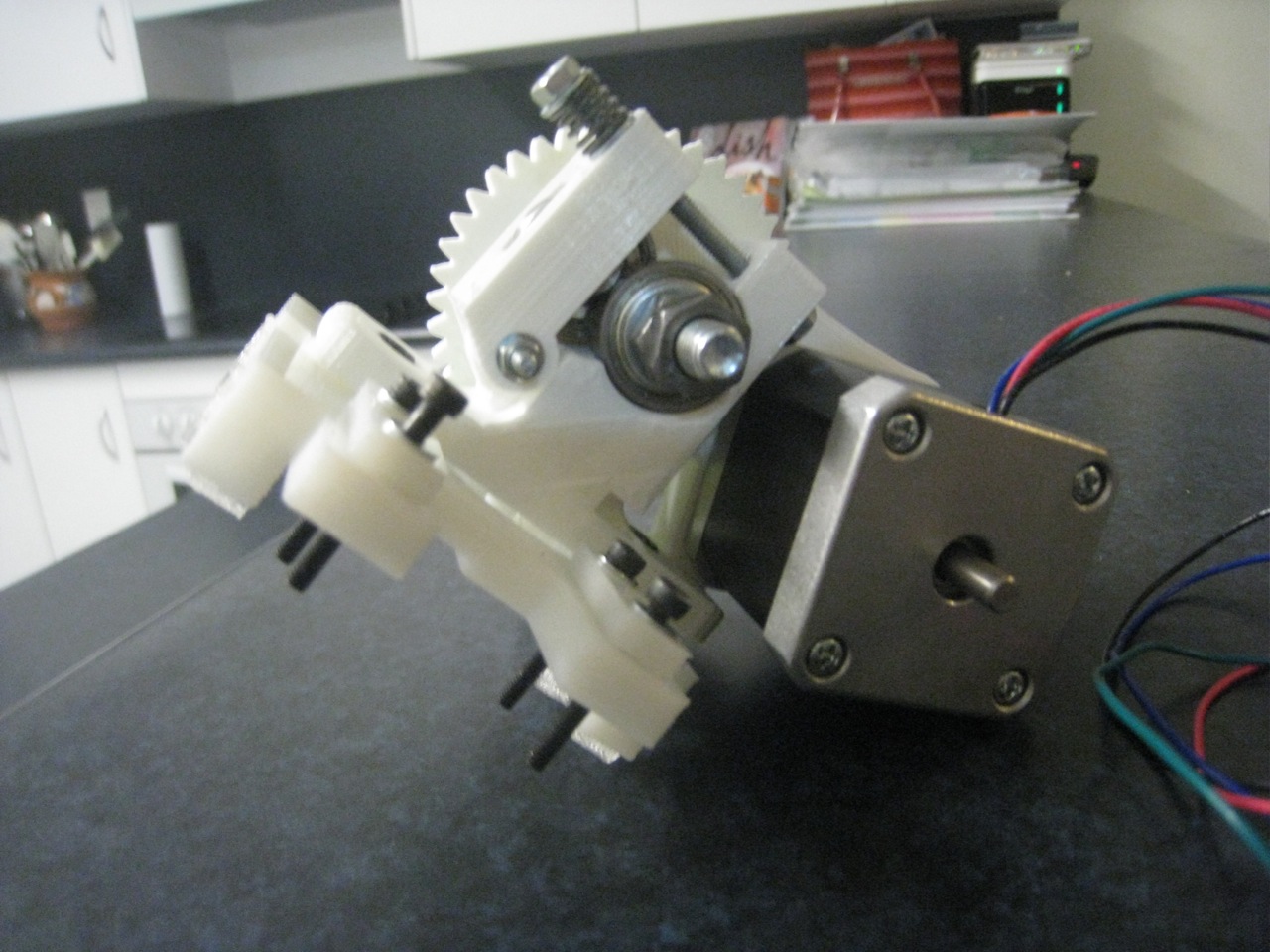
The completed extruder pieces:

All up, it was a very good test for my printer, one that I think it passed fairly well. Yesterday, I threw all the pieces in the mail. Hopefully, they’ll work great for Shulz and get him on the path to printing!

Final Assembly, and First Print

With the extruder completed, the only job remaining is to hook up the extruder motor and the hot end to the electronics. The new wire-stripper made that a much easier job.

Connecting up the hot-end

 Molex connector for easy removal
One the extruder and hot end was complete, I removed the hot end, so that I could do some extrusion calibration. Whilst some default values for Wade’s extruder are known, Greg hasn’t provided any starting values for his extruder. I started out by doing some 50mm extrusions, and calibrating using Prusa’s calculator. Once that was done, I reconnected up the hot end, and put everything together. The printer was complete!

  Finally complete

I started off by doing a few extrusion tests. They went well to start with, with the hot-end warming up, and spitting out a line of filament. I then tried to set the Z-value of the tip. Then the printer started acting strange. The Z-motors were going crazy, not spinning enough. Spinning up, then down. I couldn’t figure it out. I went to the IRC channel, but no-one was interested in helping today.

Not sure what else to do, I started fiddling with the Z-connector on the board. Sure enough, with some fiddling, the Z-motors would either work perfectly, or not at all. I took the connector off, to have a look, and discovered that one of the wires had broken inside its sheath. The intermittent connection of the wire was causing the erratic behaviour. I cut the last couple of centimetres of the cable, re-stripped and re-connected them.

The Z-nuts also kept falling out of the bottom of the Z-carriages whenever the printer was supposed to descend. I think that the problem is that the bushings are a bit too stiff, and the Z-carriages aren’t sliding smoothly along the track. To solve this problem, I glued the nuts in place, to make it easier for the carriages to come for the ride. Travelling upward’s isn’t as smooth as I would like, either. I think I’ll put a little bit of lithium grease on the Z-rods, to smooth out the travel there.

Once those issues were fixed, I tried doing a print, starting off with the standard Reprap minimug. However, I ran into more issues right away.

Extrusion Test

The extruder was frequently locking up. It would only turn for a few seconds before it would stop. Having a look at it, I found out what the problem was. With Wade’s design, the extruder turns so that it has the effect of loosing up the nut on the far side of the extruder. This is compensated for by using two nuts. Greg’s has the opposite problem. Because it turns in the opposite direction to Wade’s design, it tightens up the nuts. It keeps on doing this until the extruder binds up from the force of the nut.

I got around this problem by taking off the standard nuts, and replacing it with a Nylock nut that a lot less prone to movement. Hopefully, this will fix the problem. I then tried to print the minimug again. To increase the chance of success, I decided to add in a raft in the Sfact settings. The print started off badly, with the tip dragging through the kapton tape on the heatbed, due to being too low in some places, but then went to the centre of the print bed, and started printing at just the right height.

The raft went down perfectly, with sharp lines, and stacking nicely. However, after that, things starting going downhill. It started to print some of the minimug off the raft. It kept printing, but it was messy, as strands were just loosely dropped on top of each other.

At least the raft looks good

After a while the extruder stopped extruding properly, it was hardly outputting any filament at all. At this point I stopped the print, as it was failing badly. I then had a look at the extruder, to try and nail down this problem. It puzzled me for a little while until I realised that the small gear was turning freely on the motor shaft. I tightend up the grub screw. Hopefully, it’ll work for a while. I intend to file some flats on the motors, but unfortunately, our machinist at work has broken his hand, making it hard for me to use his help.

My main problem is that the heatbed just isn’t flat, and when it’s not flat, then you can’t get the tip close enough to the bed. I also don’t like trying to set the Z-stop when the tip is so close to the bed. It takes quite a few tries to get it so that it’s ‘just right’. I’m tempted to inverse the Z-stop, set it as an upper limit, then use the software to set the lower limit of travel. That would probably work particularly well with using Nophead’s idea of the magnetic calibrator.

 Minimug. Theoretically, anyway.

I was going to take the heatbed off, and just print on the upper steel bed, but my wife Cathy suggested that I could use one of her glass trivets. Given that it’s designed to be used as a trivet, it should be made of Pyrex. In any case, she wasn’t stressed if I broke it, as she doesn’t like it.

So after a lot of work, and a lot of problems encountered, I finally got the printer to print – something. Hopefully, I’m over the hump for the physical issues, and I can just tackle calibration for now. I think for tonight’s print, I put the minimug on the back-burner, and do a calibration cube, see how that turns out.

Greg’s Hinged Accessible Extruder

Since my Arcol hot-end doesn’t attach to the default Wade’s extruder, I had to go searching around for a new extruder. One of the Australian forum-goers suggested contacting Greg Frost, to print me up a new part. I contacted Greg last week, to get him to print me out a new base for the Wade’s Extruder. However, he quickly upsold me one of his Hinged Accessible Extruders. It arrived in the post today, to my great joy.

Greg’s Parts

The most noticeable thing is the difference in quality between Greg’s parts and Nophead’s. Nophead is justifably famous for the quality of his parts, so having a look at Greg’s gave me a better idea of what is achievable by us mere mortals.

Unlike Nophead’s parts, Greg’s parts came ‘raw’, so they needed a bit of work with a knife and drill to tidy up before the build. This gave me a good chance to have a look over the parts and the design. Greg’s design is very interesting, with some definite improvements over Wade’s. As seen by the name, the improvements are aimed towards accesibility. This is very noticeable with regards to the filament access, but it extends to all other aspects of the design.

With Wade’s design, there’s a lot of bolts which are underneath other bolts, which basically means that you have to disassemble large amounts of the extruder to work on other parts. This is noticable with the X-carriage mount. To get to it, you have to remove the motor. To remove the motor, you have to remove the hobbed bolt and large gear. And that’s the first mount. Greg’s design fixes nearly all of these problems, particularly with the innovation of the angled motor mount.

Once all the parts were clean, and the kids were in bed I got to work, assembling the extruder. Greg hasn’t released any instructions on how to assemble his extruder, it has to be done by inference from the photos on Thingiverse. If you’ve assembled a Wade’s previously, then it’s pretty easy, but if Greg wants to make his extruder more popular, then it will be assembled by some people who haven’t assembled an extruder before, and they’ll need some instructions.

One very annoying thing with the build was that the M3x10 screws that are used to hold the motor to the frame in Wade’s no longer work. Unfortuately, I was out of 20mm screws, so I had to take three 20mm screws out of my Nophead’s Z-couplings, replace them with 25mm screws, and then use the 20mm to hold the motor on. Even worse, these didn’t work! With one washer in place, the screws bottomed out on the motor, leaving the motor loosely fitted to the frame. I had to add in a second washer in to make it fit correctly. This is definitely an area that could be improved with the extruder.

A major problem was with the hobbed bolt. The hobbing on the bolt I have is very narrow, only about 3mm wide, but it lines up perfectly on Wade’s Extruder. However, on Greg’s it was quite a way out. To make it fit, I had to put 3 washers between the big gear and the extruder, to push the hobbing across. Even then, it’s ever-so-slightly out of alignment, about 1/2 mm. Hopefully, this won’t cause any issues.

Once all together, the bolt was pretty stiff, and turned slowly. Hopefully, the stepper motor will have enough torque, and this won’t end up being a problem.

The next problem I had was that I didn’t have enough short 4mm bolts to hold both the extruder to the X-carriage, and the hot-end to the extruder. Luckily, with the new extruder, I had a couple of very long 4mm bolts extra, since the Hinged Extruder doesn’t need the four spring-loaded bolts (just one) that Wade’s does. A short bit of hack-saw work later, and I had a couple of extra bolts handy. One downside: These bolts don’t have a screw or allen-key attachment, so they were slow to attach. I had to slowly tighten the bolt with a pair of pliers.

Once the Arcol was attached, I then realised that I’d need to remove it again, so that I could calibrate the E steps / mm for the extruder. Argh.

After it was all together, I decided to call it a night. All I need to do now is connect up the hot end to the electronics, then I’m good to print. I should be able to get my first print done tomorrow night! Minimug, of course.