Calibration Time

While my Prusa is printing fairly well, there’s still a lot of room for improvement. My calibration methodology so far has involved just fixing the glaring problems, rather than going through a systematic calibration process and optimising the printer’s performance at every step.

The top two tasks on my ‘to do’ list are calibration related, so it makes sense to tackle them all in one go. Seeing the success that Julian has had with his calibrations has inspired me to sit down and go through the calibration profile described in the wiki.

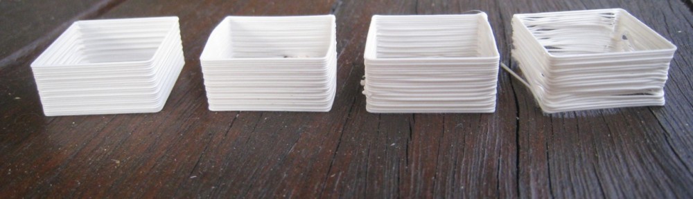
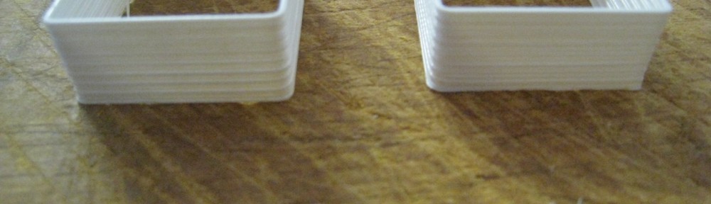
First off: Thin-walled cube. This one is used to test the layer thickness. As per the calibration procedure, I started off with 0.4mm, working my way down in 0.01mm increments – all at 30mm/s speed. 🙂

As you can see from the photos, they all turned out great, with no issues at all of the extruder tip plowing into the previously deposited layer. SFact is obviously doing a really good job in controlling the extrusion for all these different heights. As the layer thickness decreases, the fineness of the layers becomes extremely apparent.

The one on the left is 0.4mm layer thickness, and the one on the right is 0.31mm.

Stage two was looking at infill.

The first one I ran, I only had the infill solidity at 0.35. It turned out fine, perfectly flat. The second one I turned up the infill solidity to where it was meant to be: 1.0. In this one, there was a noticeable convexity to the top of the print. It was only minor, but quite noticeable.

However, I couldn’t find the setting in SFact that ‘s meant to fix the issue – ‘Infill width over thickness’. This must be one of the settings that been taken out with the move from Skeinforge to SFact. Maybe the best way to adjust this these days is by changing the ‘Filament Packing Density’ – I’ll have to check. Since there wasn’t anything more I could do here, I moved onto a third test – Oozing.

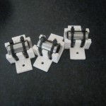
Oozing has been the biggest issue with my printer since I started printing. There’s two main issues that I have. The first is at the ‘uplift corner’. I always get a bulge at the corner where the printer stops to lift up the layer. The lifting up process causes the print to pause for a second. The ‘dribble’ from the nozzle at that point always creates a slight bulge.

The second issue is a more typical ooze issue – ‘fly aways’ at the start and end of exposed ‘towers’. This can be seen very clearly in some of my earlier prints – seen here. These problems aren’t too bad. The results can be cleaned up with a knife fairly easily, but better not to have the problem in the first place.

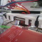
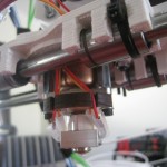
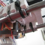
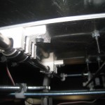
Unfortunately, I wasn’t able to make any real headway today into this problem. SFact has two main ooze-related settings – ‘Oozerate’ and ‘Filament Retraction Speed’. I fiddled with these settings, as can be seen the above photo, but without any real improvement.

As an additional step, I went and downloaded the ‘daily branch’ version of SFact. This has a lot more ooze and retraction-related settings. I tried a couple of test prints, but again, had no significant success.

I’ll keep trying with some additional settings, but I think I’ll have to go to the forums’ and ask for some help there, get the expert’s opinion.


Speed Trap

As I commented in Julian’s blog, it’s interesting to see the difference in quality that he gets between the different speeds. I haven’t noticed too much of a difference myself, but I put that more down to my lack of calibration than anything else.

I thought that I’d replicate his three-speed experiment to compare and contrast the results. I used the ‘single-wall calibration cube’ as my test object.

The four speeds were: 30, 45, 60 and 90 mm/s. They’re all looking fairly good up until the 90mm/s one. The main problem there was that the filament was going down so fast that it didn’t give the layer below a chance to cool down before starting the next layer. If I’d had some active cooling, or a larger object, I think it’d have looked great.

I didn’t notice until I’d finished doing these cubes, but my X-Axis belt was slightly loose. I think I could have got them looking even better!

Spool Finished

Finally finished printing the spool. Printed out the last couple of bits tonight, and assembled it this afternoon.

The most difficult part was the support arm that sits on the frame, the spindle. In its standard orientation, it wouldn’t fit onto my print area. I had to load it up into EasyFit, and rotate it 90 degrees. Currently my X-axis only has 155mm of travel, while Y has 175mm. Once rotated the piece fit on fine. However, I printed out the wrong one! I printed out this spindle, but it was too narrow, causing the spool to flop around. I had to print out the spindle from this page. It’s a bit tight, but should loosen up with use (and maybe some sandpaper.) I also printed up a filament guide.

Here’s the assembled spool. Looks great, and will keep my work-area a bit more tidy. As you can see, I’ve almost finished off my first roll of filament!

And a video of the spindle being printed.

Auto-Shutdown

Well, that was easy. Only a minute of searching the Reprap forums yielded the solution to this problem.

To auto-shutdown the hotend and heatbed after a print just go to the ‘chamber’ tab in SFact. Turn chamber on, then check the ‘turn off at shut down’ buttons.

Catching the Marlin

Okay, so that title was pretty contrived.

Last week, when I was having ‘shelling’ (actually backlash) issues, I made a post to the Reprap forums. One of the posters there suggested that a way to correct the ‘wiggles’ in the walls of my prints was to change across to the Marlin firmware.

This is a pretty radical suggestion, as Sprinter is currently firmly entrenched as the favorite firmware of the Reprap community. But, given that changing firmware is pretty much the easiest thing you can do with your Reprap, I thought I’d give it a shot.

Some of the touted features of Marlin are:

  • Interrupt based movement with real linear acceleration
  • High steprate
  • Look ahead (Keep the speed high when possible. High cornering speed)

Configuration was easy, Marlin uses exactly the same configuration.h file as Sprinter, so all the settings can carry through. One point of note; the Marlin firmware runs at a standard 250,000 baud rate, as opposed to Sprinter’s 115,000. The only trickiness with the firmware was the thermistor tables. Marlin didn’t have the thermistor table for my hot-end, but that was just a simple copy-and-paste job across from Sprinter’s thermistor.h.

Once uploaded, WOW, the difference is impressive. You can hear  the difference in the motor control. Much smoother and more finely controlled than Sprinter.

The printer is now exceptionally quiet. It was pretty noisy when I had Sprinter and the PLA bushings, but now with the linear bearings and Marlin, it’s super-quiet. No problems watching the TV with the printer running away behind your head. It’s probably due to the greater stepping control and better acceleration. Less ‘jerks’ on the axes.

The print quality has improved again. One of my banes – non-completely-filled top surfaces – has almost been eliminated. Surface finish is much better, as is layer stacking.

Next on my list of ‘things to work on’ will be to try and figure out how to shut down the heatbed and hot-end after a print. I’m now confident enough with my printer to leave it running unattended (once I get the spool printed for filament feed), but I want it to shut down when I’m finished. I think this can be done by adding the right G-codes to the end.gmc file, but I need to investigate how to do that.

Main things to work on now:

  • Ooze settings.
  • Solid infill, particularly on ‘top’ layers.
  • SD card printing
  • Investigate the ‘Marlin’ firmware (as per this thread)
  • Figure out how to turn off the heatbed and hot-end automatically (gcodes?)

Upgraded

One of the most amazing things about the Reprap project is that the printers can print out their own repair parts and upgrades. Today, my printer joined that club when I installed the linear bearing upgrades that the printer had printed off itself.

The installation process went fairly easily, with the main hassle trying to line up the Y-axis bearings with each other. The best way to achieve this was by only screwing in one of the two screws in each mount, leaving the mount free to orientate itself along the smooth rod.

It was a little bit noisy at first, being metal-on-metal, but a bit of lithium grease on the rods quickly fixed that up.

Main things to work on now:

  • Ooze settings.
  • Solid infill, particularly on ‘top’ layers.
  • SD card printing
  • Investigate the ‘Marlin’ firmware (as per this thread)

Linear Bearings

I’ve been having trouble printing out the parts to use the linear bearings on the Y-axis. The bases have been coming through fine, but the ‘towers’ have been coming through as blobby messes. Lowering the temperature a bit has helped.

Following on from Julian’s suggestion, I had a look at the Easyfit software he recommended. Using it, I cloned the Y-axis bearing holder three times, so that I had four of the parts on a ‘plate’. My thinking was that by printing four parts, it would give the parts enough time to cool down between each layer. I set them up with 5mm between each piece, which worked great.

This was my longest print so far, at 57 minutes. This is how the parts looked when printing was finished.

 As you can see, I still need to work on my ooze settings, but the parts looked pretty good, with no melting around the ‘towers’. My theory worked well. Here’s the parts once cleaned up a bit with a Stanley knife.

I’m really pleased with them, and the linear bearings snap into them without any troubles at all. Next up was to print up an X-Carriage. The main option is Greg Frost’s X-carriage, but I went for Joem’s version, as it allows for four, not three, bearings. However, it’s very large. If it cuts down on the X-travel too much, I might have to switch to the three-bearing version. I also printed out the version with mounting points for a fan, which I think I’ll fit in the future.

This was an even longer print, at about an hour twenty. This print had some noticeable lifting off at one corner, which came up about 1mm. This won’t affect the performance of the part, but I might have to keep the bed temperature a bit higher than 100 degrees for these larger pieces in the future.

Useful Printing

With the ‘backlash from hell’ problem solved the printer’s printing really well, enough that you can actually print useful things with it.

I’ve been experimenting with temperatures a bit, trying to find a happy medium that will print well, and still stick to the heated bed. I’ve found some settings that work quite well.

To start with, I set the heated bed temperature to 130 degrees. This results in about a 115 degree temperature at the top of the pyrex sheet. I also set the hot-end to 230 degrees. Once the first layer is complete, I turn down the hot-end to 220, and the bed to 100, which results in about a 90 degree top temperature.

These settings work great. The first layer sticks really well, and the object stays really stuck for the remainder of the print. Once the print’s finished, the bed temperature usually has to drop below 60 degrees before the object can be removed without major force. The base has that nice ‘glossy shine’

The first objects on my list of ‘real prints’ are some LM8UU Linear bearing parts to put onto the printer, and a spool holder for the filament. Here’s the first spool part:

Learn From My Fail

If you’ve been following the blog, you’ll have seen that I recently replaced the pulleys with aluminium pulleys. I’ve also been having trouble with my shells not lining up. Until yesterday, I hadn’t put two and two together, and realise that one was causing the other.

I put a post on the Reprap Skeinforge forum, showing the shot glass, and asking what might the problem be. I thought it must have been an SF issue, but the forumer’s quickly suggested that the problem was probably with backlash.

Nophead then suggested that the problem was probably the aluminium pulleys. He stated that the teeth on the pulleys are too narrow, and cause the belt to slop around on the teeth. So I pulled the Aluminium pulleys off, and replaced them with the original RP pulleys.

What a difference. So, learn from my fail, the ebay Aluminium pulleys are worthless. Video of the shot glass being printed:

Slowdown

As I mentioned in my previous post, I had issues with the last print due to the high speed. I thought I’d slow this one down.

I also thought that I should be more meticulous about keeping records of the changes I’m making. In keeping with the original ‘lab notebook’ idea for this blog, here’s the settings.

Original settings:

From ‘Speed’

  • Main Feed Rate – 60 mm/s
  • Perimeter Feed Rate – 30 mm/s
  • Travel Feed Rate – 130 mm/s
From ‘Raft’
  • First Layer Main Feed Rate – 35 mm/s
  • First Layer Perimeter Feed Rate – 25 mm/s


Changed Settings:

From ‘Speed’

  • Main Feed Rate – 20 mm/s
  • Perimeter Feed Rate – 15 mm/s
  • Travel Feed Rate – 30 mm/s
From ‘Raft’
  • First Layer Main Feed Rate – 15 mm/s
  • First Layer Perimeter Feed Rate – 15 mm/s

And the result:

As you can see, it came out looking nearly identical to the first part. So it looks like speed isn’t the problem. As another test, I decided to print out the ‘single wall calibration piece’. It came out beautifully.

Then I thought I’d try the 10x40mm piece. I stopped that one after about 8mm, it was just turning into a sludgy mess. I thought then that to print a piece like that, I’d need to turn down the temperature, or use active cooling. I thought I’d try turning the temp down.

To get a better picture of what was happening, I thought I’d print out the ‘ultimate calibration piece’. To start with, I turned the temp down to 225 degrees, (from 230).

You can see in the picture, that the first couple of ‘hanging beams’ are sagging a bit. I then turned the temp down to 220. The remainder of the object printed fine, but the sagging was noticeably reduced.

I stopped the print at that point, since the ‘shelling’ problem (can be seen in the problem above) was distracting me. It’s clearly seen in the ‘reprap shot glass’, and it looks like SF is not correctly shelling the object, and creating proper G-Codes. I thought I’d better fix that problem first, before messing with the temperature.