Installing Pronterface

There are a few different software packages (aka host software) which can be used to controlled a Reprap. There is Pronterface, Repsnapper, and the creatively-named RepRap Host Software. Kliment’s pronterface (aka Printrun) is one of the most supported and popular at the moment. It had a lot of recommendations behind it, so I thought that it would be the best one to go with.

It was a little bit tricky to install, mostly because if you use a mac you also have to install wxPython as well as pyserial, which requires a command and installation from a command line.

Pronterface also needs to be run from the control line:
python pronterface.py

Running the program bought up the following screen:

First up, I tried to connect to the electronics. For some reason, the usb serial ports which I had previously used to connect Arduino to the electronics weren’t showing up, so I had to reinstall that software. It seems like it disappears every time the computer is rebooted, so I’ll have to track that problem down.

Next up, I tested the electronics, to see if they were correctly reading the thermistor on the hot-end. I set up the hotend to the electronics like so:

After a little bit of fiddling with the wires (I didn’t even strip them) I was able to get it to correctly read 22 degrees.

My next steps will be to install skeinforge inside of pronterface, and I’ll hook up a stepper motor and make it spin.

Updating Sprinter Firmware

Auzze’s RAMPS board came with Sprinter firmware already installed, but unfortunately, I’m not able to use this as-is. The thermistor’s that came with the hot end were 200k thermistors, and the pre-installed firmware was set up for the standard 100k thermistors.

I asked Auzze the best way to go about this, and he suggested the following method:

1. Download the Arduino Software
2. Download the Sprinter firmware.
3. Make changes to the firmware’s configuration.h file, then upload.

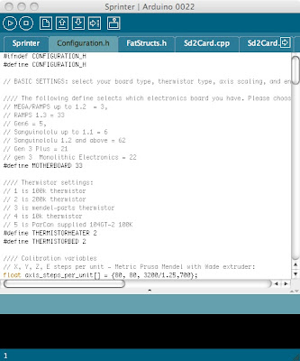
Downloading and installing the Arduino software from arduino.cc was extremely easy, as was downloading the Sprinter firmware. Once I opened up the sprinter.pde file in Arduino, the screen looked like this:

The following settings in the sprinter configuration.h file had to be changed:


#define MOTHERBOARD 33 


#define THERMISTORHEATER 2
#define THERMISTORBED 2


float axis_steps_per_unit[] = {80, 80, 3200/1.25,700}; 


const int X_MAX_LENGTH = 170;
const int Y_MAX_LENGTH = 180;
const int Z_MAX_LENGTH = 110;

I was then ready to upload. The first time I tried to upload it didn’t work; didn’t recognise the board. I then realised that I need to specify the board to load onto. In the arduino software, I had to set the board to ‘ATMega1280’, and the USB port. However, there were no USB ports to choose from on the list.

The default ports that came with the software were only Bluetooth ports, so I had to run the other piece of software that came with the Arduino package (FTDIUSBSerialDriver). This added two extra USB port options to the software, which enabled the computer to connect up to the board.

Once this was done, the new firmware loaded quickly onto the board. Of course, I’ve got no way of testing it yet, so I’ll install Pronterface next. Thanks for the great after-sales support, Auzze!

Wiring Diagram for RAMPS

In my last post, I was uncertain as to what some of the I/O plugs were for on the RAMPS. Fortunately, I was able to find it pretty quickly on the Reprap wiki:

so E0 / E1 are for the extruder motors, D10 is for the extruder heater, and D08 is for the heated bed.

I still need to find out what Aux4 is for.

update: Aux 4 is for a as-yet-unsupported LCD screen. The SFJW firmware apparently supports it, but it’s very alpha at the moment. (It doesn’t even support 200k thermistors!)

Almost There

One major part and one important tool arrived this week.

The first thing that arrived was an IR thermometer – a Fluke 561. My wife was instantly convinced as to its usefulness when I showed her how to take the kid’s temperature very quickly using it. This should come in very handy when trying to calibrate the prusa, and trying to get the temps on the heated bed and the hot-end correct.
 Temperature gun in its case
Temperature gun in action
One thing I like about this thermometer is that you can plug in a K-type temperature probe. The 561 comes with a velcro-strap thermometer that you can wrap around pipes. One major downside to this thermometer that I didn’t realise when I purchased it is that the K-probes will only work up to 100 degrees C. (For no good reason that I could determine.) The other feature that would be nice would be to be able to turn the laser off. You can do this when you you’ve got a probe plugged in, but not at other times.
The other thing that arrived this yesterday was the electronics kit. I got this from ‘Auzze’ – one of the Australian members on the Reprap forums. He sells a complete kit, including endstops, plugs and an SD card reader.
RAMPS 1.3 electronics kit
There’s a few things that I’m unsure of with this kit:
  • I can see where the voltage comes in for the shield. Does the Arduino need its own voltage supply?
  • What’s the ‘Aux 4’ input / output for? Is it for an LCD screen?
  • The ‘X’ ‘Y’ ‘Z’ outputs are pretty straight-forward. I presume the ‘E0’ and ‘E1’ are for the hot-end and heated bed respectively, but I’m not certain.
  • I’m not sure which plugs are for the temperature sensors – is it the ‘T0’, ‘T1’ and ‘T2’, or the ‘D8’, ‘D9’ and ‘D10’?
It looks like I’ll have to do a bit of research before I start plugging things in. 
That’s almost everything I need for the Prusa. The only thing left to get now is the hardware kit. I suspect that it will be a while yet – it’s coming by sea-mail. At least I should have a pretty good idea on the electronics by then.

Assembling the Arcol Hot End

As I mentioned in a previous post, I purchased an Arcol.hu hot end. This week, I started assembling it. Lazlo’s got some good instructions up on his website, so I was able to follow those and assemble the hot-end without any dramas at all.

The biggest hassle with assembling the hot-end is trying to protect the thermistor. It’s quite fragile, and the arms can break quite easily. So naturally enough, you start off by wiring up the thermistor. The very thin connecting wires were quite fiddly to try and strip as well.

The connected thermistor

After that, you need to connect up the power resistor in a similar way.

Power Resistor

Next up is to fit the power resistor into the heating block. It’s quite interesting to see that most of the hot part of the hot-end is made of aluminium. I haven’t chatted with Laslo, but I suspect that it’s because the thermal gradient on aluminium is extremely steep. Away from the active heating area, it will cool down extremely quickly. I suspect that this is why Arcol design has such a short hot zone.

This also makes it easy to fit the power resistor, as you can then safely use aluminium foil as a wrap around the power resistor to ensure a tight fit.

The fitted power resistor
The next step is to put in the thermistor and seal it into place using fire cement. In Lazlo’s build instructions he usually attaches the nozzle first, probably to make sure that there’s enough space for it to screw it. I didn’t want to risk contaminating the nozzle with any rogue cement, so I did it separately. I first wrapped up all the bits that weren’t going to get fire cement on them with Kapton tape, then put in the cement. I then left it to dry for a couple of days.
Cemented-in thermistor with Kapton tape
Kapton removed
That’s the hardest parts of the build completed. The remainder is very easy, just basically screwing together the remaining components. The lower frame is first:

Lower mounting frame
The wires are protected with heat-resistant covers then the nozzle assembly is attached to the frame. The covers weren’t quite long enough to prevent the thermistor’s trailing leads from touching each other, so I wrapped some more Kapton tape around them to stop them shorting out.
 
Nozzle fitted to lower assembly
Rotated view

At this point, the instructions on the website diverge slightly from the current hot-end. The instructions on the website are for version 3.0 of the hot-end, but the version he’s currently selling is version 3.01. There are only small differences, mostly down to an improved heat-sink. It’s pretty easy to guess the correct way to put the remaining pieces together.

The completed hot-end

In all, quite a fun and interesting build. My only gripe is that the PEEK block doesn’t sit totally flush with the lower mounting assembly. This results in a very slight angle to the nozzle. You can see this in the photo below. I can’t really see how this could be a problem for printing though. The millimetre or two of offset isn’t going to cause any problems, as long as it’s consistent.

Slight angle on nozzle

ABS

The ABS filament have finally arrived. Took 12 days in the post to get here from Victoria. (Thanks, Australia Post.)

It’s from Lybina, and it looks pretty good. The dimensions are 2.93mm on the long axis, and 2.84mm on the short axis. That makes it a lot more consistent than other filament out there, but you’d expect high tolerances from an Australian manufacturer.

Prices were pretty good too, so I was more than happy to go Australian in this case. I expect that it should melt down nicely.

Still more parts

Still more parts this week, but one of them I can actually do something with!

PCB Heat bed from Reprap source

Aluminium pulleys. These are supposed to give a better quality of print, by having less slop and backlash. A pretty cheap printer upgrade.

A wand-type temperature probe for my (forthcoming) temperature gun.

Hobbed bolt from Arcol.hu.

And finally, and most importantly, the hot end! For my hot end, I decided to go for one from Arcol. It looks like a great design. Things I like about it:
  • A super-short heated zone. From what I’ve seen during my research, the Arcol hot-end probably has the shortest heated zone of any hot end. This should greatly reduced extruder force.
  • A removable and exchangable nozzle in 0.5mm and 0.35mm sizes.
  • An excellent support structure. Unlike most nozzles, it has a fully triangulated structure. This should reduce the movement of the nozzle head during printing, resulting in more accurate prints.

The best thing is that this is the first part that I can actually do something with! I can start assembling it right away.

Temperature Controller

One of my other hobbies is home-brew beer. However, here in Blackwater, it gets hot, and controlling the temperature of the fermenter is very difficult. The best I’ve been able to do is wrap a wet towel around the fermenter, and have the end of the towel in a bucket of water. As the water evaporates, it keeps the fermenter cool. This works moderately well, but it only maintains a temperature of about 24 degrees, and requires frequent checks.

To make life easier, a lot of home brewers use a dedicated fridge. I was lucky enough to get an old upright freezer for free from a friend. To then use it for home-brewing I just needed a temperature controller to keep the fridge at my ideal fermenting temperature.

There are no fully-built temperature controllers available which just plug in-line to the fridge and control its temperature. (Which seems strange, you think there’d be a market for it). However, there’s plenty you can buy which needs to be wired up. Since I’m stepping up into the world of physical computing with the Prusa, I thought it’d be a good small project to start with.

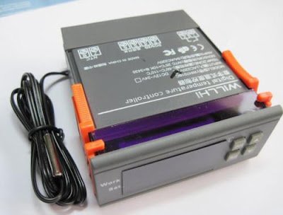
There’s heaps of temperature controllers on eBay, that look like this:

Willhi temperature controller

So I picked one up. Unknown to me at the time, there’s actually two types of temperature controllers. Ones that do heating OR cooling, or ones that do heating AND cooling. They look almost identical, and sell for the same price. I bought the OR controller, thinking I was buying the AND controller. I thought the AND controller would be more useful, since you could then wrap a heat belt around the fermenter, while its in the fridge. Then, no matter if the temperature was hot or cold, the fermenter would then stay at a constant temperature.

To wire these up, I bought some cheap $3 extension cords from Bunnings, to cut up and wire inline. A problem with these controllers is that they have exposed 240v connectors at the back. Not good from a safety perspective.

Exposed 240v connections.

So I bought a hobby box and some cable glands to put the controller in. Holes then needed to be cut into the box. This was the hardest part of the operation. I needed a 70mm by 32mm hole, and three 19mm holes in the back. After more than an hour of drilling and sawing, I could immediately see why Dremel tools are so popular. I wasn’t able to finish it that day, as my biggest drill bit was 12mm. I had to go borrow a Unibit from a guy at work. The end result:

Front of box
Rear of box

A bit rough around the edges but pretty good. The edges don’t worry me, as they’ll be hidden behind the faceplate. I then fitted the controller inside it, and wired it up, as I thought it should be, judging from the text on the top of the controller.

The wired up controller

The wiring was a bit tight inside the box, but not too much of a cause for concern.

 Box all ready to go
After I got to this stage, I plugged it in, (just the inlet power only) to give it a quick test. It all looked good, but it was operating in heating mode, not cooling mode. I fiddled with the buttons, but I couldn’t figure out how to put it into cooling mode, nor set the other features (compressor cooldown time, temperature deviation allowed, etc.)

At this point, I realised that there were two different types of temperature controllers, and that I had got the lesser model. Oh well, having the heater unit simultaneous with the cooling would only be useful two me for a couple of weeks per year. If I really want to go that way, I can just switch controller over every morning and afternoon.

I wrote off to the ebay seller, hoping to get a pdf manual from them. After shooting the email off, I had a bit of a look amongst the other ebay auctions, to see if they had some of the manual text in there. In one of the auctions for the better controller, I saw a manual which said that you need to hold down the ‘set’ button to access the other settings. I tried it with my controller, and it worked! I was all good to go, or so I thought.

A day later, I got an email back from the ebay seller, with the manual in it. Included in the manual was a wiring diagram, and I had it wrongly wired it up. One of the leads was meant to go direct from input to output, and another was meant to be wired in series with the switch. Fortunately, it was easy to change, I just had to loosen off the glands, and reconnect the cables.

Once it was wired-up again, I took it to work, to have the sparky give it a look over, and compare it to the wiring diagram. He gave it his thumbs-up, so I bought it home and plugged it in.

The working controller

A great thing with this setup is that I’ll be able to use it to make Lager beer (which has a much lower fermenting temperature, never achievable with temperatures here), as well as put it properly through the lagering process. I think I’ll give that a try next winter, when the outside temperatures mean that the fridge gets too cold for ale yeast. So instead of using a heater element, I’ll just use colder yeast.

Update:
Since there’s been some interest in this controller, and it’s manual, I’ve PDF’d it and uploaded it. You can find it here.

Kapton!

Only one part arrived this week: Kapton tape.

I decided to go for the 50mm wide tape. It had a good balance of price / mm, and it will only need a few strips to cover the heated bed, minimising the amount of hassle required to perfectly line up each join in the tape.

Moving bits

This week, the PSU and the stepper motors arrived.

I decided early on in speccing out the printer that I wanted to go with a heated bed. It generates much higher quality prints, but with no need of a raft. One of the problems generated by having a heated bed, however, is that you need almost 20 amps of power. Each stepper motor (or more correctly, the stepper motor driver) is rated for about 2 amps, and the heated bed can use up to 9 amps when warming up. Add on the hot end, and you’re nearly at 20 amps when starting off a print. Fortunately for power bills, this drops down a lot once the hot end and bed are up to temp.

I contemplated going route of other people and modding an desktop computer ATX supply. But in the end I decided to go for this one. It’s cheaper than a ATX supply that’s rated for 20 amps, and I don’t need the 3v and 5v outputs. This PSU is designed to recharge batteries for radio-control vehicles, but it makes a good 12v lab bench supply.

Also arrived are some stepper motors from AusXMods. The specs on these are pretty good, get the full amount of torque required (50 Ncm) at low volts and amps. These motors should easily be able to handle the load required by the Prusa.