Category Archives: reprap

Visual Illusion

In Julian’s blog, he talked about one of his recent designs – a piece that was designed to answer a challenge on the Thingiverse blog.

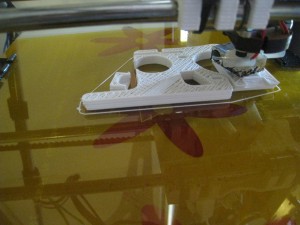
He noted that he hadn’t printed it out yet, so I thought that I’d have a go this afternoon, see just how well it turned out. I downloaded the piece from Thingiverse, and printed it out.

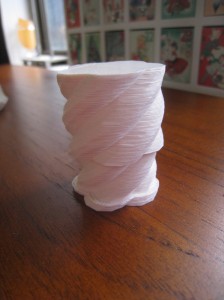
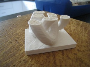
The printing went quite well:

Trying to take a decent video showing the illusion was by far the hardest part of this mini-project. This was my best attempt, which I think did the trick. Unfortunately, these balls were a bit big for the job.

Recent Printing

I haven’t been doing much printing lately, the usual hassles of life catching up with me.

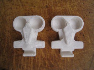
I’ve printed up a few more of the earbud holders over the last few weeks, for people who are jealous of the ones that I gave out during Christmas.

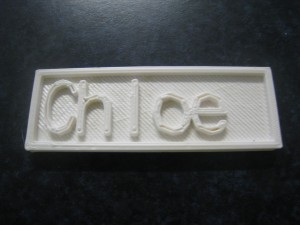
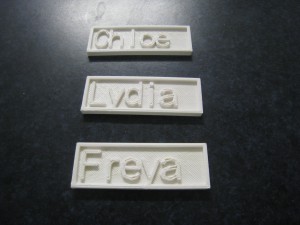
A couple of weeks ago, I spotted this page over on thingiverse, which generates some nameplates. I thought that these looked like a lot of fun, and an easy way to print name-tags for the kids’ bags and stuff.

I printed out a few of them one evening while my wife was having a craft night with her friends. They loved them, so I ended up printing out lots of them for their kids as well.

Last week, I went through and updated the software toolchain – SFact, Pronterface and Marlin. It never fails to amaze me just how much improvement comes through in the software, over the space of two months.

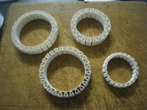
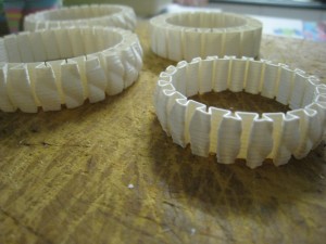
The only other thing of note that I’ve printed out lately is some bracelets. Slightly strange story behind these – when I was speaking on the phone with my Mum a few weeks ago, she said that she had a dream that I’d printed her out a bracelet. So, to make the prophecy self-fulfilling, I found a design on Thingiverse and printed a few out for my Mum and daughters. Turned out very nicely.

I adjusted the size of the first couple of larger ones by playing with the ‘scale’ setting in SFact, but this didn’t work very well with the smaller bracelets. So I downloaded the OpenScad file, and modified the variables in that. That worked really well to generate the smaller bracelets.

The printer’s working really well these days, completely hands-off. I just hit ‘print’, then walk away. The printer even shuts itself down at the end of the print, and always produces nice results.

Proposal: Part Per Month Project

This is a copy of the post I made to the Australian Reprap forums.

The Part Per Month Project

Background

Back when Reprap was young, it was a principle of the project that all printers would print out and give away one set of parts, to help the project grow. This idea has largely fallen into disuse over the last couple of years, but the idea is a good one. However, printing out a full set of parts is a fairly daunting task, and requires a fair amount of printing time and material.

In addition, there are numerous organisations and individuals out there who could benefit from receiving the ‘seed parts’ for a 3D printer.

This proposal is an idea that I’ve had for a while. Now I’ve got my printer up and running to a decent level of quality that I can make parts that I would be willing for someone else to use, I thought I’d put it to the group.

Proposal

As the name suggests, this project will seek to enlist members to print out one part per month. These parts will be sent to recipients who can benefit and use these parts to build their own 3D printer.

The printer will be divided up into the following parts:

  1. Frame Vertex w/ Foot No. 1
  2. Frame Vertex w/ Foot No. 2
  3. Frame Vertex w/ Foot No. 3
  4. Frame Vertex w/ Foot No. 4
  5. Frame Upper Vertex No. 1
  6. Frame Upper Vertex No. 2
  7. Z-Motor Mount 1
  8. Z-Motor Mount 2
  9. X-End Idler
  10. X-End Motor
  11. X-Carriage
  12. Extruder
  13. Extruder Gears
  14. Y-Motor mount and X & Y-Motor pulleys
  15. Z-Axis couplings x 2 plus Endstop holders x 3
  16. Bushings x 12
  17. Bar clamp x 8
  18. Belt-clamp x 4 plus rod-clamp x 2

As can be seen, this will require eighteen people in the project. At the start of each month, a recipient will be selected from a group-agreed list. The members of that project will then print out their pieces and mail them off individually to the recipient. This keeps the administration of the project to a minimum, but does require the project members to keep their word and mail off their parts.

Just about all of these parts can be printed in an hour or less, and only use a few grams of plastic, so it only represents a modest investment. Most likely, the postage for each part will cost you more than the plastic.

Many of us aren’t part designers, or wiki writers. We don’t contribute much back to the Reprap community other than through helping people in these forums. This project will be a way for us to give back to the Reprap community, using the very tool that community helped us to create.

Call for Members and Recipients

If you’re interested in joining this project, please respond to this thread, stating which part you’d like to print. Personally, I’d like to print part ‘7’.

In addition, I’m also seeking to create a list of recipients. If you know of worthwhile recipients, post them up and we can discuss and add them to the list. Suggested recipients: Hackerspaces, schools, uni labs, maybe even as prizes for STEM competitions. Since this is an Australian forum, I’d suggest keeping it to Australian recipients for now.


FAQs

Here’s some questions I’ve anticipated. I’ll add more to the list as they get asked.

Q: I only print in PLA / ABS! How will mixed parts work?

A: I can’t see any problem with having mixed printers. My only suggestion is that people who only print in PLA sign up for the ‘PLA recommended’ parts first, ie bushings, and ABS-only printers sign up for the ‘hot’-pieces first (X-Carriage, Extruder).

Q: I don’t want to print out any parts, but I’d like to help in other ways!

A: If you’d like to help, let me know. There are plenty of other ways you could assist. For example you may wish to donate a couple of metres of ‘starter’ filament, or machine up a hobbed bolt, or a couple of bits for the hot-end. Make a suggestion!

Q: Which set of pieces should we print? There are so many variations, ie, printer feet, linear bearings, etc.

A: To start with, we’ll only print up the ‘Prusa standard’ parts list. I’d suggest that we fully embrace the ‘iteration 2’ Prusa. To ease confusion, we’ll probably create a github repository, with only the PPMP parts in it.

But I don’t want to be too rigid. If someone’s willing to donate the linear bearings, then we may go for LB pieces. Likewise, if someone is willing to print up the extruder and the gears, then that person can choose which one they print. Depending on the number of people, and their willingness, we may also choose some pieces such as the ‘combined frame axis and Z-Motor Mount’ parts.

Q: What if we don’t get eighteen people involved?

A: If we only get nine people, then I’d suggest that we keep the ‘one part per month’, just have different parts on alternate months, and thus the project will donate one full set every two months.

Q: Sounds great! When do we start?

A: I think it’d be best if we target the start of April as the starting date. This will give everyone enough time to sign up to the project, practice ‘their’ pieces, and be ready to go in the start of April.
A Helping Hand

A few days ago ‘Schulz’ made a post on the Australian forums. He was looking to buy a modified Wade’s Extruder that would fit on the Arcol hot-end. Those who’ve read through this blog think that this story sounds quite familiar.

So, taking pity on a fellow sufferer, I offered to print him up a Greg’s accessible extruder for him for free.

First thing up was to find the STL files. Looking at the parts posted on Thingiverse, it looked like the STL files posted there weren’t pre-compiled for the Arcol hotend mount.

I get around that limitation, I downloaded the OpenScad file also published along with it. Opening up the file it looked good, but wouldn’t compile without a bunch of warnings. It was missing some configuration files that were meant to go along with it.

At first I tried having a look at Thingiverse, to see if the missing configuration files could be found there. Unfortunately not. I then had a revelation. I went to Github, and did a search for Greg Frost. There he had his fork of the Prusa files there. Looking in the list, I saw a newer version of the extruder file, and all the configuration files that it was looking for.

Once I had all the right configuration files, the extruder compiled just fine. I then added in the options for the groovemount, and the Arcol hot-end. For some reason, the groovemount option didn’t compile in correctly, but the Arcol mount did, which is all that I was looking for.

I then exported the file to an STL, and loaded it up in Pronterface. The estimation came up as three hours, fifty minutes. Three hours later, the print finished.

What struck me during the print was all the solid layers. I only used my standard 35% fill, but it printed with a lot more solid layers. It must be a feature of Greg’s design to include lots of solid reinforcing layers.

In all, I was pretty happy with the print. It doesn’t look quite as good as Greg’s extruder that’s on my machine, but it’s relatively close. Interestingly, mine required less cleanup than Greg’s did, but his surface finish is superior.

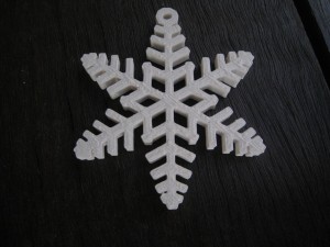
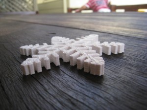
Printing out the object gave me a great sense of admiration for Greg’s design. It’s by far the most complex print I’ve ever done. Whilst the snowflake’s were complex, they were only complex in a two-dimensional manner, and were just a extrusion of that two-dimensional shape. The extruder is a true 3-D shape of high complexity.

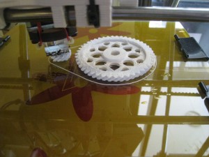
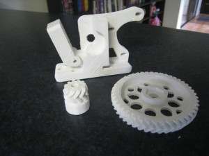
After I did the extruder, I went to do the gears. I didn’t want to print out the standard gears, so I found some STL files for some herringbone gears. The herringbone gears mesh together more tightly, so there’s less backlash from the extruder. Also, even though they are a more complex shape, I think that they’re more forgiving for poor printing.

The gears printed out fairly well. My main concern for the print was that the top of the small gear would get too mushy from too small a print area. To get around that, I put in some ‘orbit’ around the print. Unfortunately, I forgot how oozy my hot-end is. It meant that there was a lot of fine strings all around the print that needed to be cleaned up at the end.

The teeth on the large gear printed fairly well. The teeth on the small gears not so well. They were a bit blobby, and needed some cleanup. They tidied up pretty well, and I think that they’ll work fine. They seemed to mesh together nicely.

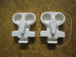
The completed extruder pieces:

All up, it was a very good test for my printer, one that I think it passed fairly well. Yesterday, I threw all the pieces in the mail. Hopefully, they’ll work great for Shulz and get him on the path to printing!

Hall-Effect Endstops

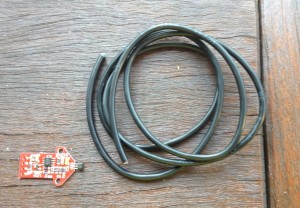
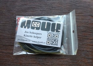
I made a little purchase in the middle of December, and there was a nice package waiting for me when I got home from holidays – Hall Effect endstops!

For those who aren’t familiar with the Hall Effect, it’s the voltage difference generated by a magnetic field. They can be used as a non-contact distance-measuring device. Hall effect sensors are used in various devices, most notably DC motors with fixed magnets, as a timing measure. The wiki page can be found here.

Its advantage is that it’s a non-contact, adjustable endstop. The problem that I have with the current endstops is that adjusting them is a pain. You have to have them attached fairly tightly to prevent them from moving during normal operation, but then trying to loosen them and adjust them by a small fraction of a mm is fiddly. This isn’t a problem for the X or Y-axes, which don’t require so much precision, but I find adjusting the Z-axis ‘just so’ to be very time-consuming and inaccurate. Lots of back-and-forth until the distance is ‘right enough’.

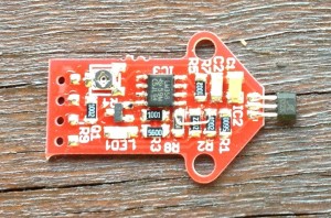
So, I purchased these Hall-effect endstops from mauk.cc. He makes these, and sells them fully assembled for 9 Euros each. At that price, I couldn’t resist giving them a go. I’m going to use this endstop to replace the Z-axis microswitch.

Due to limitations in the firmware, you can’t just set the printer to stop at a particular distance from the endstop. (Though that would be extremely nice.) It operates as a standard endstop, with an ‘on’ or ‘off’ signal. However, you can adjust (via a trimpot), the distance at which the ‘on’ signal activates. Thus, you can easily and quickly adjust the distance of the printbed to the nozzle.

I’ll set this up over the weekend, see how well it works.

A Welcome Return

Back!

I had a good break over Christmas, going down to Brisbane for a couple of weeks. Didn’t receive any reprap-related Christmas presents. This was the closest one I got.

Mad science! The essence of 3D-printing!

Haven’t done anything Reprap-related for the last while. The grandmothers really enjoyed the printed snowflakes that the girls had decorated, and everyone was very impressed that I’d made them on a 3D printer. Except my brother-in-law, of course. ‘Yeah, we’ve got about four 3D-printers at work.’

I had a guest around just a couple of days ago. He was interested in the Prusa, particularly since the last time he was around, the printer was down with a broken extruder. I printed out one of my ear-bud holders for him. It was good to just sit down and do a print, without having to mess around with settings, or software updates, or any other drama. The print turned out beautifully, too. A great demonstration for my guest.

I’ve got a couple of interesting projects in line for this year, I can’t wait to get started on them!

Praxis

This weekend, I’ve just been having fun printing out things.

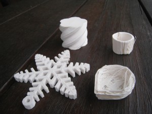
First up, I printed out a few of these snowflakes. This piece gave me a lot of grief during the week, trying to figure out the right settings to print it. It’s a real testing piece. Lots of sharp corners will test the limits of your printbed for adhesion on the first layer, and it’s an absolute nightmare for retraction. If your retraction isn’t perfect, it turns ugly, extremely quickly.

At one time during the week, I had my retraction spot-on. However, I hit the perimeter-speed bug in SFact, which prints out the perimeter of the first layer at 60mm/s. That was way too quick for this complex piece, so I had to upgrade SFact, which then means all the retraction settings were obsolete, and I had to start back from scratch. I got them sorted out on Saturday morning, and I’ve been having fun just printing ever since.

I’ll be printing out four of these snowflakes. My daughters are going to decorate them, and them give them to their grandmothers. Should be a nice Christmas present from them. Here’s a video of the snowflake in print. Have a look at all the retractions / relocations during this one layer!

Next up I printed up a screwable jewellery box. I thought that this would be an excellent piece to demonstrate just how well the printer is working now.

The box turned out beautifully, and screws together perfectly.

Just for comparison, here’s how far I’ve come in two months:

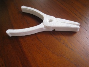
Next up, I printed out a pair of pliers. Just because!

I also lost a couple of prints during the week. For some reason the extruder was skipping steps. I tightened everything up on the extruder, re-mounted the motor and motor gear, but still had issues. Turned out one of the extruder motor wires was loose. It was being pulled too tight by the x-carriage and losing connection. So I rotated the motor to give the cables more slack, and re-connected the wires. All good!

Slic3r, redux

I was thinking that I didn’t give Slic3r a fair shake last time. Doing 60mm/s and 0.2mm layers was probably a bit too much. I don’t think any skeining program could have held up to those requirements on my printer.

To be fairer, I thought I’d do another earbud holder, but this time at 30mm/s and 0.33mm layers, which are my current SFact settings, do a direct side-by-side. Here’s the results:

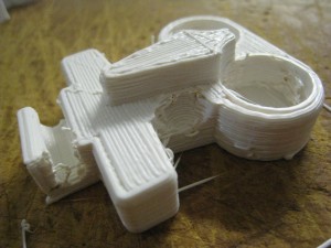
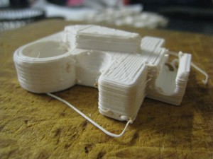
The earbud holder turned out fairly well (especially once cleaned up).The primary difference between the SFact and the Slic3r output is the flyaways – a function of the retraction settings. SFact’s retraction is clearly superior at this point in time. However, if your hot-end isn’t particularly oozy like mine is, then Slic3r may be a better option.

Watching the print, Slic3r definitely had some areas in which it was superior to SFact. SFact always starts each new layer at the same point. Slic3r instead just goes to the nearest point on the perimeter to where the fill finished. This helps reduce the ‘blobby corner’ effect that SFact produces with me. Its fill logic is a lot better as well, reducing unproductive travelling.

I’d really like to have a try at some of the other fill types that Slic3r has – it might produce better fill performance, and maybe end up with some better surface finishes than you get with SFact’s standard fill.

I’m thinking that the Slic3r might actually be a good choice for beginners. It’s definitely not as imposing or scary for people starting off, and produces quite good results.

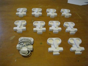
Here’s all the earbud holders I’ve printed so far:

This is one thing that I’m really enjoying about doing this lot of earbud holders for Christmas presents – it’s giving me a good chance to refine my printer, and do a lot more side-by-sides, experimenting with just one variable at a time.

Argh!

I was printing out the 3D-knot as a bit of a demonstration / vanity piece. However, when the print was at 77%, I accidentally disconnected the USB cable!

Unfortunately, the cable I have at the moment isn’t long enough to reach my printer, so I use a USB-extension cable which is a bit prone to coming apart.

It was looking really good, with only a little bit of lifting up at one corner.

 I noticed that a few of my recent pieces have had this lift-up issue. To combat it, I’ve made the following changes:

  • Add in a few extra shells on first layer only.
  • Drop down the nozzle so its a bit closer to the bed (0.13 to 0.18mm)
  • Reduce the ‘Additional height (ratio)’ in ‘bottom’ tab to 0.3
  • Give the bed a really good clean. There were a few grease marks causing the filament to stick badly, which would then start off the lift-off.

That’s really helped on the last couple of earbud holders I’ve printed out. I’ve also figured out how to take some really nice videos:

Okay, I’m really going to have a good look at SD card printing now.

Removing Extra Shells

I’ve had the suspicion for a while that the ‘extra shells’ setting in SFact was causing a few of my prints to print out sub-optimally. Now, I’ve got some proof. Some 608 bearings arrived during the week, so I thought that I’d print out some Z-axis stabilisers. I’ve seen that the walls on my prints have a bit of ‘wobble’ in them. This wobble isn’t on the Y-axis, it’s only confined to the X. I’m thinking that the Z-axis is moving a bit, creating the X-axis wobble.

However, when my first print was done, it looked like this:

There was a clear gap between the inside wall and the outside wall of the bearing holder. This gap went all the way down. I think what’s happened is that SFact creates extra shells. However, once these shells are created, there isn’t enough space left for SFact to then do some infill.

To try and combat the problem, I went into SFact, and removed the extra shells on all layers except the base layer. I then tried out the same print again, and it came out perfect.

At the moment, I’m wondering why SFact even has the ‘extra shells’ feature at all. Just how necessary is it?

With another print of the earbud holders, I tried removing the extra shell on the base layer as well, but I ended up having trouble with my first layer. Once the infill started, the head would sometimes pick up the outside line, tearing it off the bed. Adding back in one extra shell fixed this problem.

Once two Z-axis stabilisers were finished, I fitted bearings in them. (They just pushed in with only a moderate amount of force. Perfect sizing.) I then mounted one on the X-motor side. (The one on the X-idler side will have to wait for some endstop fiddling). I then printed out another earbud holder for comparison. It came out beautifully. The combination of the Daily Branch of SFact, Marlin 1.0 Beta, and the Z-stabilisers is making my prints look absolutely fantastic.

This part needed absolutely no clean-up at all. This is the way it came out of the printer.

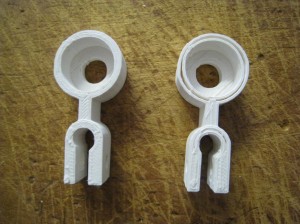
Before Z-stabiliser on left. After Z-stabiliser on right. Notice particularly the fill goes right to the edges much better.

Stabilisers on top holder.

In related news, the ooze problem seems to have disappeared. Have a look at the photo below. The vertical hole has printed perfectly, no strings at all. I’ve got my suspicions as to what’s fixed the problem, but I’ll leave that for another post.