One of my other hobbies is home-brew beer. However, here in Blackwater, it gets hot, and controlling the temperature of the fermenter is very difficult. The best I’ve been able to do is wrap a wet towel around the fermenter, and have the end of the towel in a bucket of water. As the water evaporates, it keeps the fermenter cool. This works moderately well, but it only maintains a temperature of about 24 degrees, and requires frequent checks.
To make life easier, a lot of home brewers use a dedicated fridge. I was lucky enough to get an old upright freezer for free from a friend. To then use it for home-brewing I just needed a temperature controller to keep the fridge at my ideal fermenting temperature.
There are no fully-built temperature controllers available which just plug in-line to the fridge and control its temperature. (Which seems strange, you think there’d be a market for it). However, there’s plenty you can buy which needs to be wired up. Since I’m stepping up into the world of physical computing with the Prusa, I thought it’d be a good small project to start with.
There’s heaps of temperature controllers on eBay, that look like this:
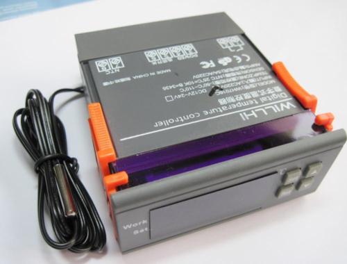
So I picked one up. Unknown to me at the time, there’s actually two types of temperature controllers. Ones that do heating OR cooling, or ones that do heating AND cooling. They look almost identical, and sell for the same price. I bought the OR controller, thinking I was buying the AND controller. I thought the AND controller would be more useful, since you could then wrap a heat belt around the fermenter, while its in the fridge. Then, no matter if the temperature was hot or cold, the fermenter would then stay at a constant temperature.
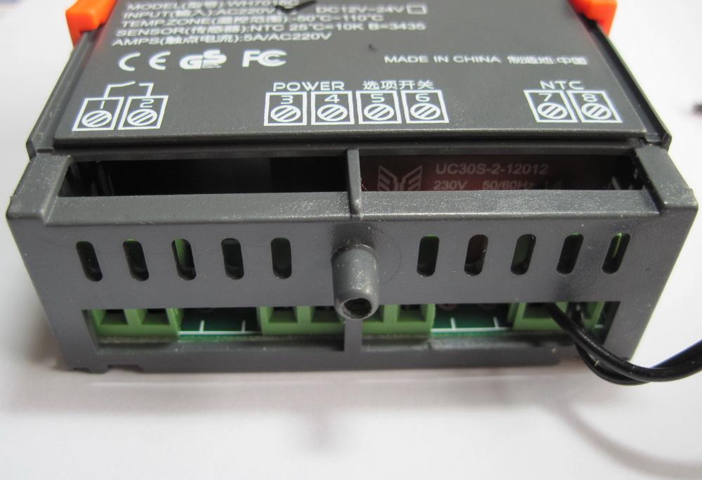
To wire these up, I bought some cheap $3 extension cords from Bunnings, to cut up and wire inline. A problem with these controllers is that they have exposed 240v connectors at the back. Not good from a safety perspective.
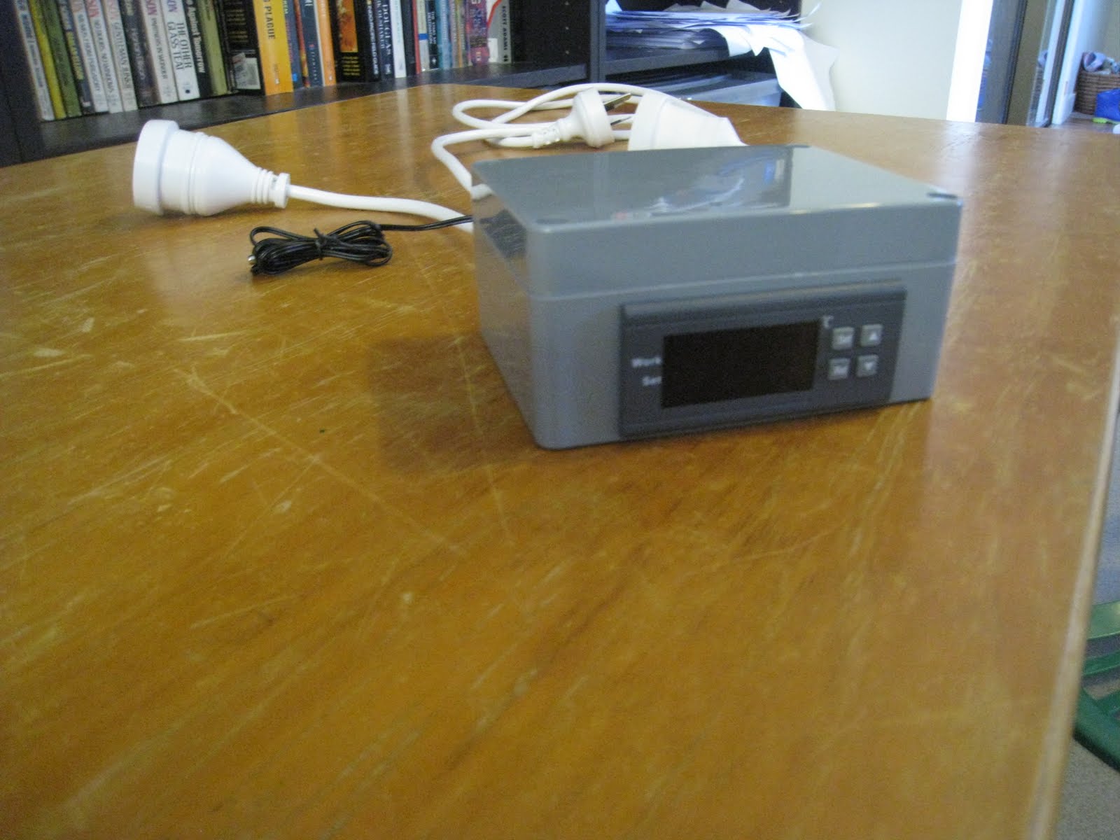
So I bought a hobby box and some cable glands to put the controller in. Holes then needed to be cut into the box. This was the hardest part of the operation. I needed a 70mm by 32mm hole, and three 19mm holes in the back. After more than an hour of drilling and sawing, I could immediately see why Dremel tools are so popular. I wasn’t able to finish it that day, as my biggest drill bit was 12mm. I had to go borrow a Unibit from a guy at work. The end result:
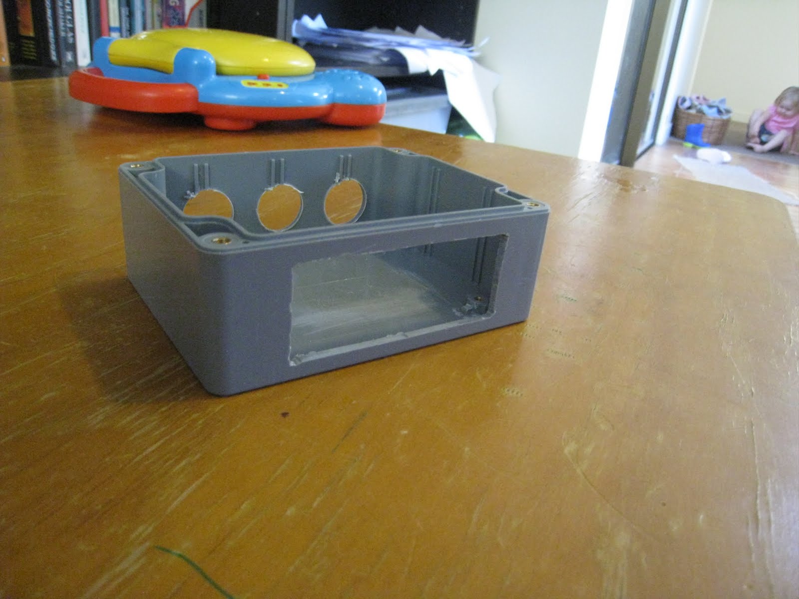

A bit rough around the edges but pretty good. The edges don’t worry me, as they’ll be hidden behind the faceplate. I then fitted the controller inside it, and wired it up, as I thought it should be, judging from the text on the top of the controller.
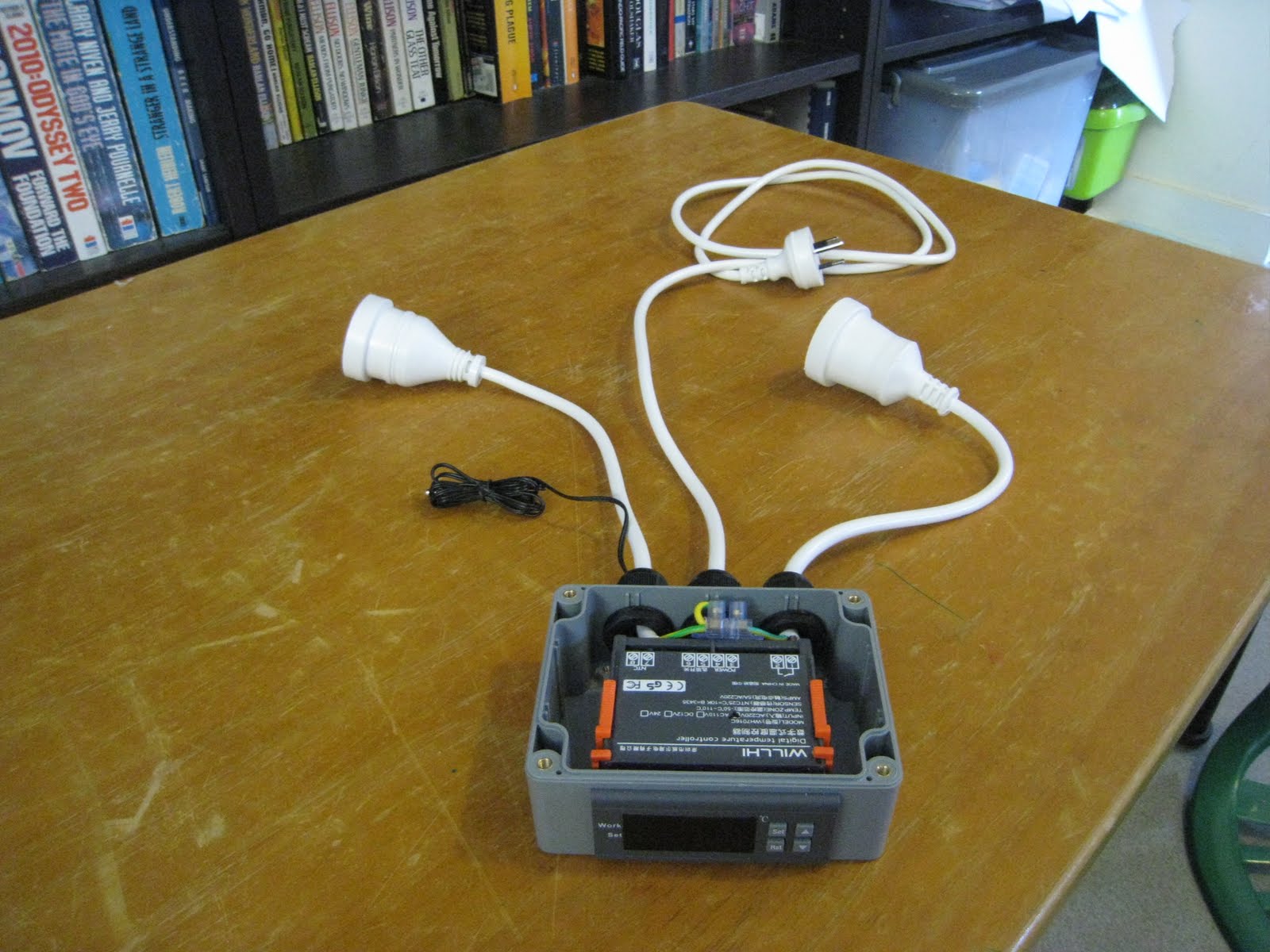
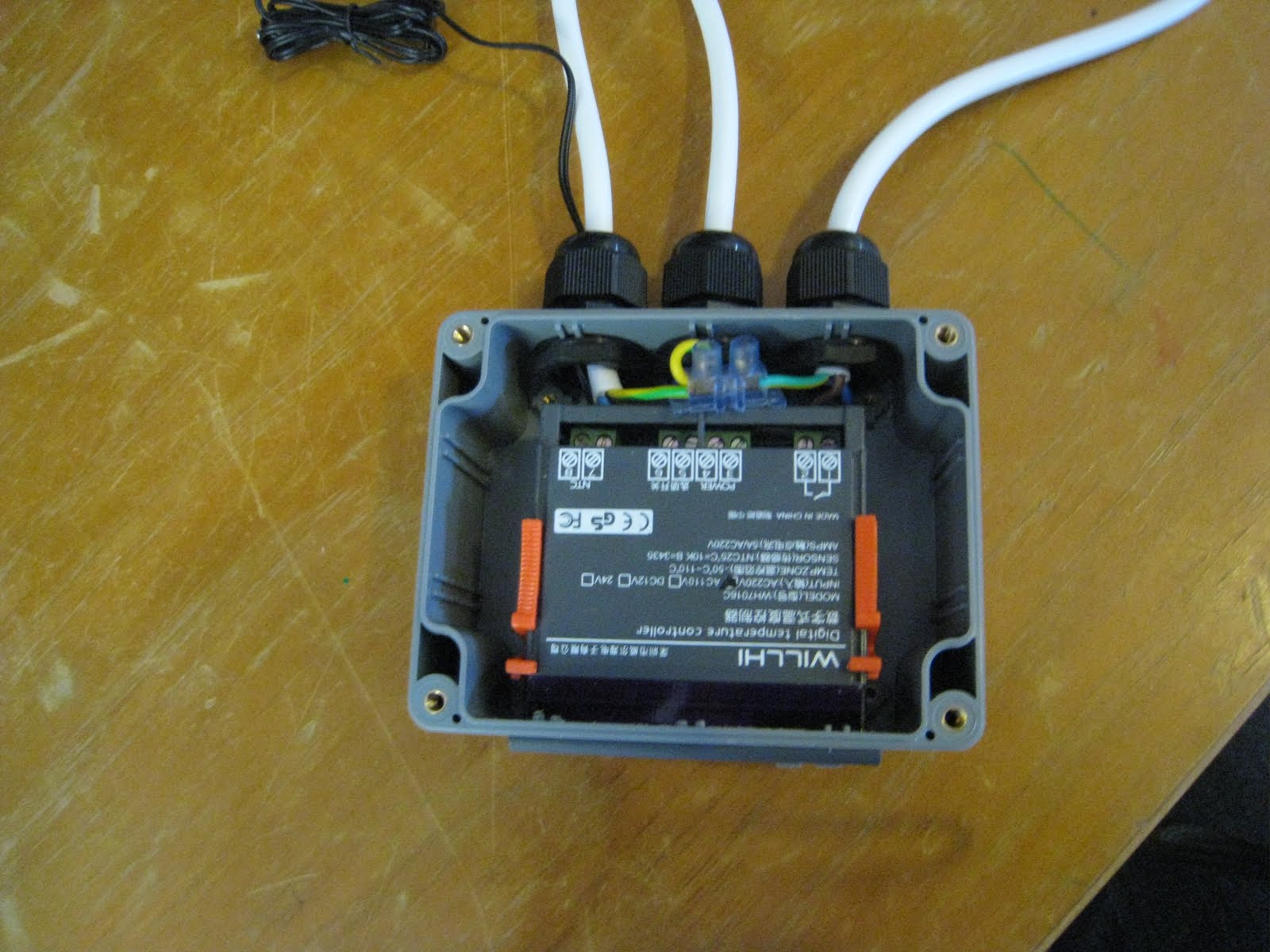
The wiring was a bit tight inside the box, but not too much of a cause for concern.
At this point, I realised that there were two different types of temperature controllers, and that I had got the lesser model. Oh well, having the heater unit simultaneous with the cooling would only be useful two me for a couple of weeks per year. If I really want to go that way, I can just switch controller over every morning and afternoon.
I wrote off to the ebay seller, hoping to get a pdf manual from them. After shooting the email off, I had a bit of a look amongst the other ebay auctions, to see if they had some of the manual text in there. In one of the auctions for the better controller, I saw a manual which said that you need to hold down the ‘set’ button to access the other settings. I tried it with my controller, and it worked! I was all good to go, or so I thought.
A day later, I got an email back from the ebay seller, with the manual in it. Included in the manual was a wiring diagram, and I had it wrongly wired it up. One of the leads was meant to go direct from input to output, and another was meant to be wired in series with the switch. Fortunately, it was easy to change, I just had to loosen off the glands, and reconnect the cables.
Once it was wired-up again, I took it to work, to have the sparky give it a look over, and compare it to the wiring diagram. He gave it his thumbs-up, so I bought it home and plugged it in.
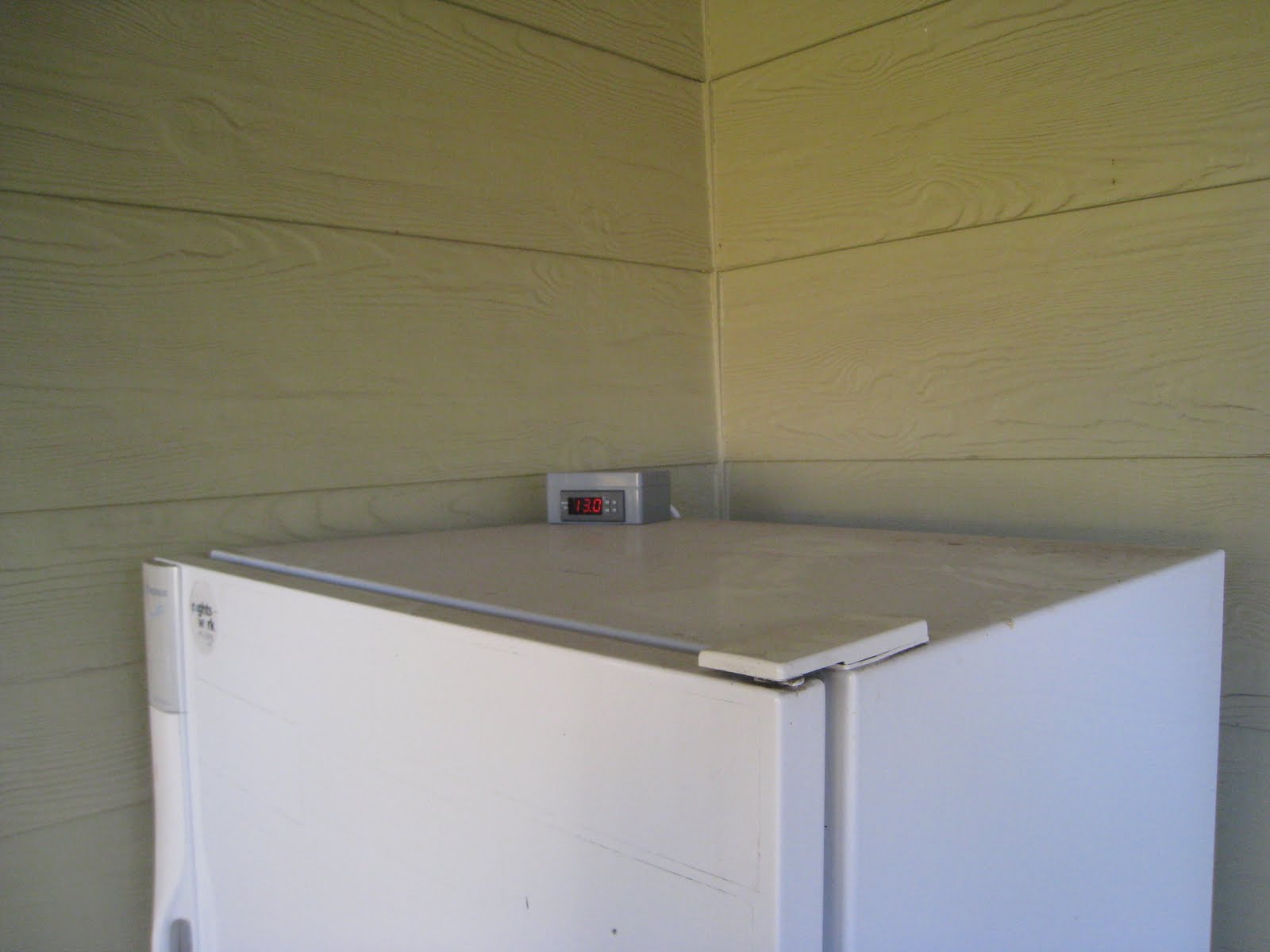
A great thing with this setup is that I’ll be able to use it to make Lager beer (which has a much lower fermenting temperature, never achievable with temperatures here), as well as put it properly through the lagering process. I think I’ll give that a try next winter, when the outside temperatures mean that the fridge gets too cold for ale yeast. So instead of using a heater element, I’ll just use colder yeast.
Update:
Since there’s been some interest in this controller, and it’s manual, I’ve PDF’d it and uploaded it. You can find it here.
Thank you so much for putting so much info on this controller.
I intend to put the controller with a small central heating pump in line with my pool pump, to curculate three solar panels for my pool.
This looks like you could have a timer, controller and pump for some £100 to fit to solar panels.
You might not be able to do that. The amperage rating of this temperature controller is probably not high enough. I can’t recall the amperage rating, but I think that it maxes out at about 5 or 10 amps. That’s enough for a fish-tank heater or a fridge, but not for a water pump.
I’ll check the amperage rating and get back to you.
After checking, the temperature controller is only rated for 240v / 5A.
Good article. I am going to use 2 of these to replace the mechanical hot water cylinder thermostats driving motor valves. These never stay consistent at their set temperature.
There is no problem overcoming the 5 amp internal relay limit which incidentally should be ok for most central heating pumps (75 watts). Use a second mains voltage relay 10-15 amps (bigger project box!) or for larger currents control a contactor. Loop mains through their internal relay to the 230 v ac coil on the external relay. For fridge compressors with largish starting currents and inductive motors, I would suggest the 10-15 amp rated external relay. If you use the internal relay, the contacts may weld together making you think the controller is not doing anything! I do not think they brought out the internal d.c voltage to the rear panel (12 or 24 volt). It should be easy to find inside and would be useful to control solid state or low voltage relays.
I believe these controllers do heat OR cooling, but often in process control you need two separate relay channel outputs.
Isn’t it frustrating with some of these Chinese products, that the biggest problem is finding a suitable hobby box which may cost the same. But try building this controller for the price it sells for.